Operation Manual ServoOne Supply Unit
63
ID no.: 1101.21B.6-00 Date:04/2020
5.2.7 Setting DC link capacitance
6.
The settings for the DC voltage regulator depend on the DC link capacitance of
the entire multi-axis system. You will nd the DC link capacitances in the operation
manuals for the supply unit and the DC axis controller in the technical data in the
chapter Appendix.
y Add together the DC link capacitances of all controllers connected to the multi-
axis system.
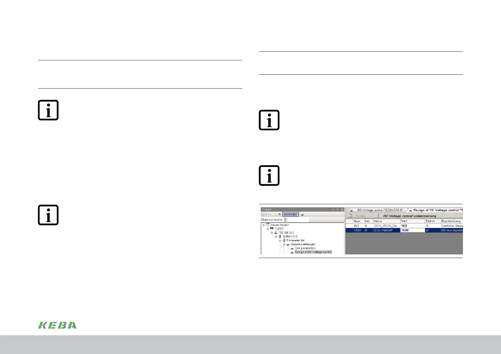
y Set the total value for the DC link capacitance in P-1500 (in µF).
NOTE:
The maximum overall capacitance of the multi-axis system DC link for a
ServoOne supply unit BG5 (incl.) must not exceed 10,000µF, for BG6a (incl.)
20,000µF and for BG7 (incl.) 25,000µF.
y Set the relative controller dynamic performance for the voltage regulator in
P-0405.
Recommended value: 100%.
NOTE:
In all circumstances the parameter P-0405 must be activated by "double-
clicking" the "value" eld and using the "Enter" key, even if you do not make
any change. Otherwise the automatic conguration of the voltage regulator will
not be undertaken.
Figure 5.4 Parameter editor - parameter P-0405 and P-1500
5.2.6 Automatic identication of the DC link capacitance and
the equivalent time constant for the current regulation
5.
The DC voltage regulator in the supply unit regulates the DC link voltage to an
internally specied xed setpoint. The regulation is dependent on the DC link
capacitance in the multi-axis system and the equivalent time constant for the
current regulation. Both values can and should be determined using the automatic
identication.
NOTE:
The maximum overall capacitance of the multi-axis system DC link for a
ServoOne supply unit BG5 (incl.) must not exceed 10,000µF, for BG6a (incl.)
20,000µF and for BG7 (incl.) 25,000µF.
y Prior to starting the automatic identication, set the setpoint for the DC link
voltage to 700V
DC
in parameter P-0410 "CON_VCON_VdcRef".
y Start the automatic identication by setting parameter P-1501 "SCD_AT_
VdcCAP_Con" to START(2).
As soon as the parameter changes to the value READY(0), the identication procedure is
complete.
The values determined for the total DC link capacitance (P-1500) and the equivalent time
constant for the current regulation (P-0406) are now available for the conguration of the
DC voltage regulator.
NOTE:
In the next step the value determined for the total DC link capacitance
(P-1500) chap.5.2.7, p.63 must be checked for plausibility and, if
necessary, replaced with the value known. The setpoint for the DC link voltage
(P-0410) chap.5.2.8, p.64 should also be set.
Commissioning
 Loading...

