Operation Manual ServoOne Supply Unit
20
ID no.: 1101.21B.6-00 Date:04/2020
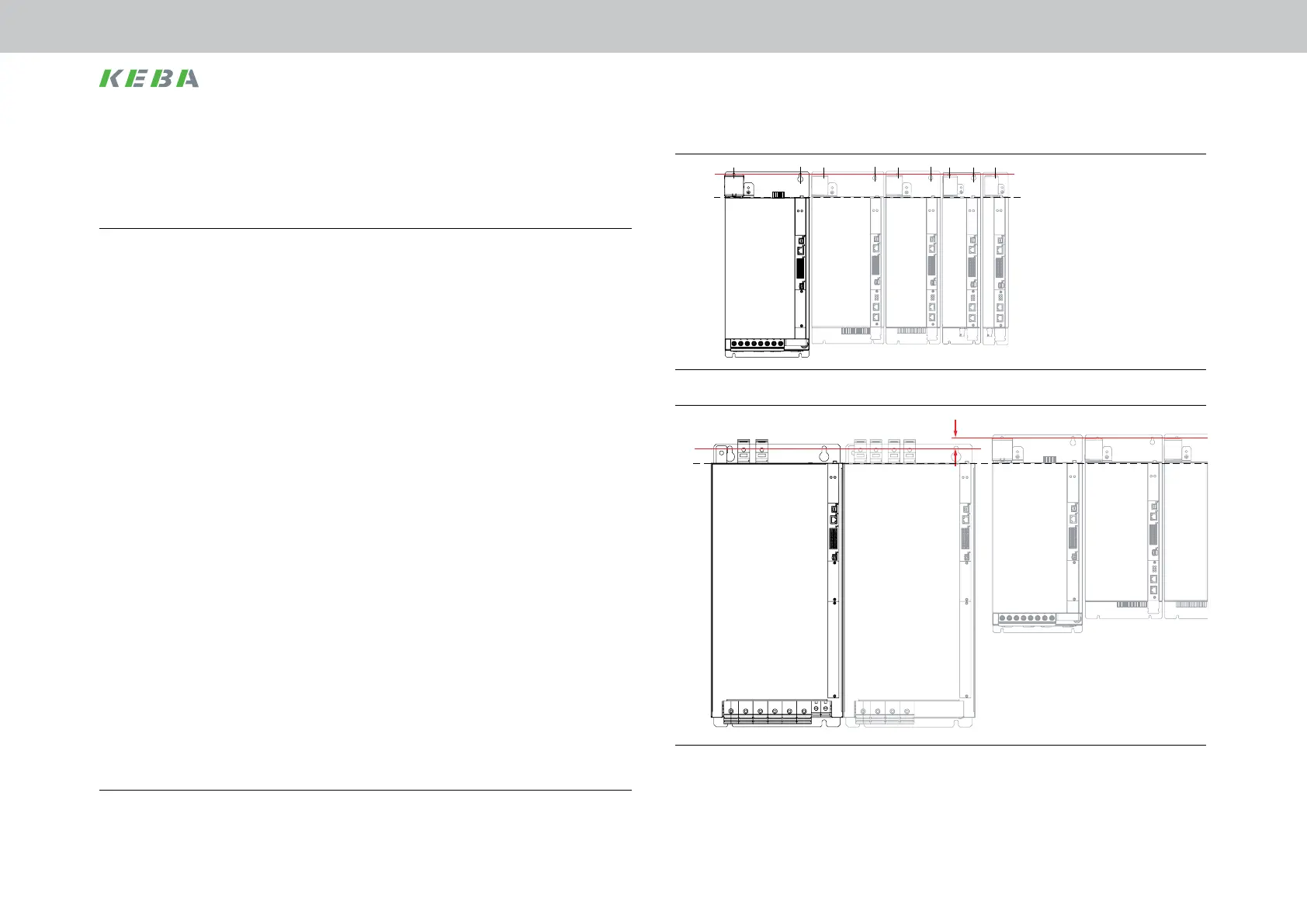
ServoOne DC BG1
ServoOne DC BG2
ServoOne DC BG3
ServoOne DC BG4
ServoOne
Supply unit BG5
B
A
Figure 3.8 Butt mounting axis group with liquid cooling and supply unit BG5
ServoOne DC BG1
ServoOne DC BG2
ServoOne DC BG3
ServoOne DC BG4
ServoOne DC BG5
20 mm
ServoOne DC BG6a
with liquid cooling
ServoOne
Supply unit BG6a
with liquid cooling
B
A
Figure 3.9 Butt mounting axis group with liquid cooling and supply unit BG6a
3.4 Mounting supply unit,
liquid cooling housing variant
1.
Arrange the devices starting from the supply unit to the right (up to ServoOne
DC BG5) or left (from ServoOne DC BG6a) sorted in descending order by power
rating to minimise thermal interaction. Pay attention to the notes on effective EMC
installation prior to mounting the devices and components in the switch cabinet.
• AlignthesupplyunitBG5andallServoOneDCaxiscontrollersinalinealongthetopedge
ofthedevices(seelineAinFigure3.8).ThisactionisnecessarytobeabletosupplytheDC
powerusingthepre-assembledcables.
• AlignallServoOneDCaxiscontrollersandthesupplyunitBG6ainalinealongthetopedge
ofthedevices(seelineAinFigure3.9).MovedownthemountingboresforDCaxiscontroller
BG6aandthesupplyunitBG6byapprox.20mm(seeredlineBinFigure3.9).Thisactionis
necessarytobeabletomaketheDClinkconnections.
• AlignallServoOneDCaxiscontrollersandthesupplyunitBG7inalinealongthetopedge
ofthedevices(seelineAinFigure3.10).Movedownthemountingboresforthesupplyunit
BG7byapprox.28mmandfortheDCaxiscontrollerBG6abyapprox.20mm(seeredline
BinFigure3.10).Inaddition,adistanceof≥40mmmustbemaintainedattheside(inthe
guretotherightofthesupplyunitBG7).ThisactionisnecessarytobeabletomaketheDC
linkconnection.
2.
Mark out the position of the tapped holes and the pipe ttings on the backing plate.
Drill holes and cut a thread for each xing screw in the backing plate.
Note the mounting distances. Also pay attention to the bending radius of the
connection cables. For dimensional drawings/hole spacings see Figure 3.8 to
Figure 3.10 and Table 3.2.
3.
Mount the supply unit vertically and butt-mounted in a row on the backing plate.
The contact area must be bare metal.
4.
On screwing the hose connections (not included in the scope of supply) into the
pipe ttings, lock the pipe ttings using a 22mmopen-ended wrench to prevent
damage due to the application of torque to the device.
Pay attention to a perfectly sealed connection without leaks (e.g. using Teon
sealing tape).
You will nd further notes on the liquid cooling in chap.A.4, p.80.
Mechanical installation
 Loading...

