Operation Manual ServoOne Supply Unit
76
ID no.: 1101.21B.6-00 Date:04/2020
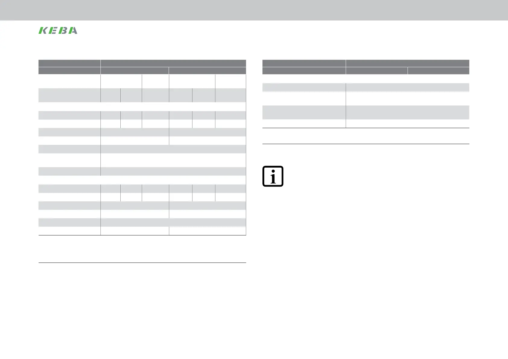
Size BG6a
Device SO84.115.Sxxx.x SO84.170.Sxxx.x
Brake chopper power electronics
1)
Responsethreshold
2)
[V
DC
] 820
Peakbrakingpower[kW]
software/hardware-side
143/157
Minimumohmicresistanceofanexternal-
lyinstalledbrakingresistor
4.7Ω
Continuouschopperpower[kW] 10
1) Optional for liquid cooling: internal braking resistor (mounted on the base of the cooler) on request
2) Minimum switch-on time 250µs
Table A.5 Brake chopper power electronics, BG6a
NOTE:
The maximum overall capacitance of the multi-axis system DC link for a
ServoOne supply unit BG6a (incl.) must not exceed 20,000μF.
Size BG6a
Device SO84.115.Sxxx.x SO84.170.Sxxx.x
Mainsinputvoltage
(±10%)[VAC]
400 460/480 400 460/480
RegulatedDClinkvoltage
[VDC]
650 770 770 650 770 770
Input, mains side
Continuouscurrent[A
ACeff
] 115 115 96 170 170 142
Peakcurrent
1)
[A
AC
] 195 195 163 245 245 204
Switchingfrequency[kHz] 8 4
Continuouspower[kW] 80 118
Powerdissipation
2)
[W] 2500
Asymmetryofthemains
voltage
±3%max.
Frequency[Hz] 50/60
DC link output
Continuouscurrent[A
DC
] 115 97 97 170 144 144
Peakcurrent
1)
[A
DC
] 195 165 165 246 207 207
Continuouspower[kW] 75 110
Peakpower
1)
[kW] 127 160
DClinkcapacitance[µF] 4240
Internalfuse(X11) 200A 200A
Note: Technical data apply for wall mounting and liquid cooling housing variants as a function of the mains input voltage and the
regulated DC link voltage
1) For 10s
2) Approximate values
Table A.4 Technical data, BG6a
Appendix
 Loading...

