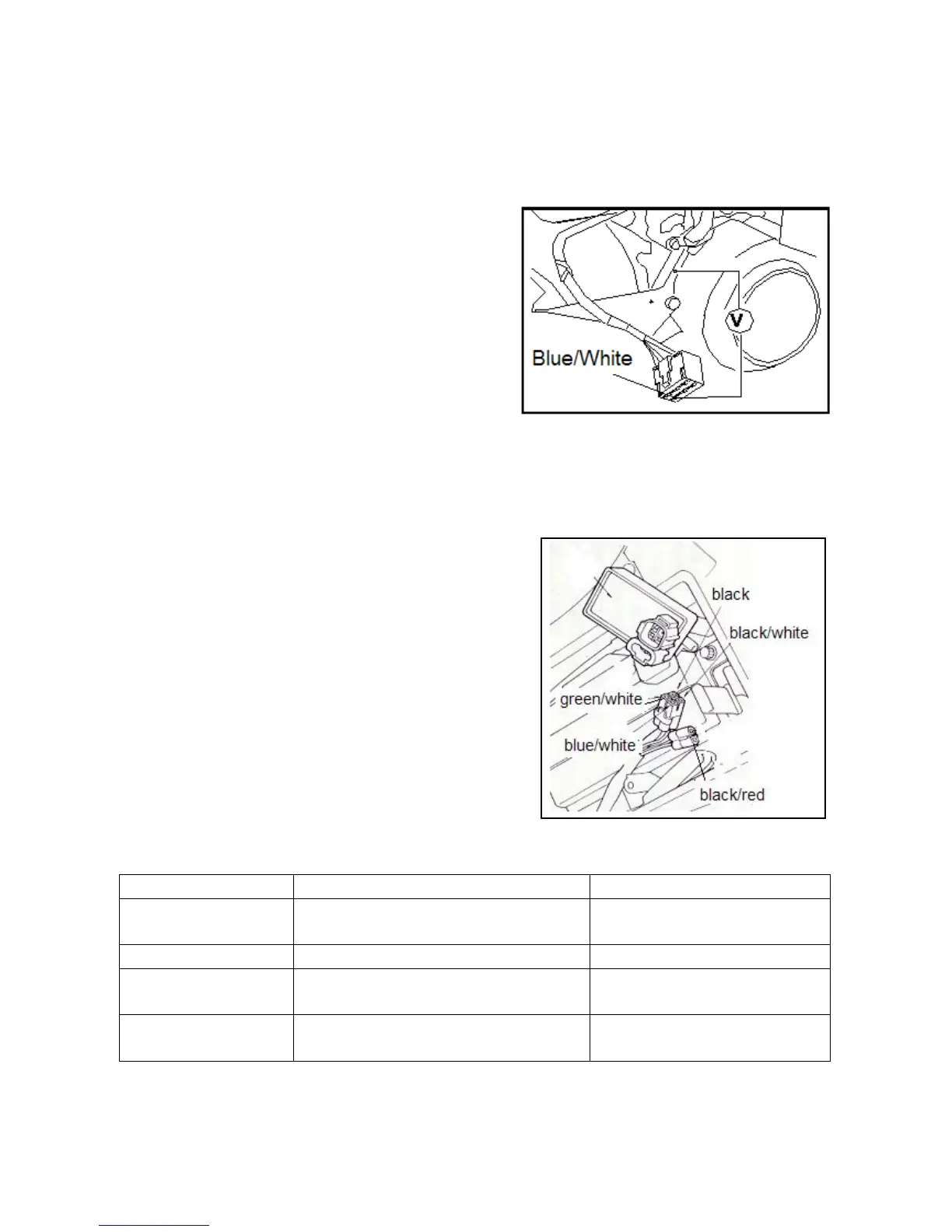
EasyManuals Logo

KEEWAY RKV125 User Manual

KEEWAY RKV125
164 pages
To Next Page IconTo Next Page
To Previous Page IconTo Previous Page
Page #71 background imageLoading...
Page #71 background image
green/white.
Min. voltage: higher than 1.7V.
* Attention
Please do not touch the metal parts of testing probe with your
fingers while measuring the voltage, or you will be shocked.
Please take care.
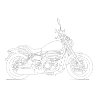
When the peak voltage measured at connector of CDI
assembly is abnormal, take down the protecting plate on the
right side of vehicle and remove connector of magneto.
Trigger (blue/white) is connected with a shunt.
When the measured voltage at CDI assembly terminal is
abnormal, but measured voltage at magneto terminal is
normal, it indicates that the connector is of poor contact or wiring is broken.
When measured results at both sides are abnormal, the trigger is damaged. Please refer to items listed in Diagnosis
Table and check.
2.4 CDI Assembly
2.4.1 System Inspection
System inspection
Remove CDI assembly and check components related to the
ignition system at wiring terminal.
2.4.2 Inspection
Remove CDI assembly and check if connectors are loose or corrosive.
Item
Measuring terminal
Standard Value20℃)
Main switch
RedRed/White
On continuity when main switch is
“OFF”.
Trigger
Blue/White-White/Green
100-200Ω
Primary coil of ignition
coil
Black/WhiteBlack
0.4Ω±10
Secondary coil of
ignition coil
Blackspark plug capnot including spark
plug
3-5.5KΩ±10

Table of Contents

Questions and Answers:

Question and Answer IconNeed help?

Do you have a question about the KEEWAY RKV125 and is the answer not in the manual?

KEEWAY RKV125 Specifications

General IconGeneral
Engine TypeSingle cylinder, 4-stroke, air-cooled
Fuel SystemCarburetor
Transmission5-speed
Front SuspensionTelescopic fork
Front BrakeDisc
Rear BrakeDrum
Cooling SystemAir-cooled
Seat Height770 mm
Weight135 kg
Fuel Tank Capacity17 L
Rear SuspensionDual shock absorbers

Related product manuals