Features and Functions 4
Keysight 34970A/34972A User’s Guide 157
Using the alarm output lines
Four TTL alarm outputs are available on the rear-panel Alarms connector. You can
use these hardware outputs to trigger external alarm lights, sirens, or send a TTL
pulse to your control system. You can assign an alarm to any configured channel
and multiple channels can be assigned to the same alarm number. Each alarm
output line represents the logical “OR” of all channels assigned to that alarm
number (an alarm on any of the associated channels will pulse the line).
You can configure the behavior of the alarm output lines as described below. The
behavior of the alarm annunciators on the front panel also tracks the alarm output
configuration. The configuration that you select is used for all four alarm output
lines. A Factory Reset (*RST command) clears all four alarm outputs but does not
clear the alarm queue in either configuration.
– Latch Mode: In this mode, the corresponding output line is latched true when
the first alarm occurs and remains asserted until you clear it by initiating a new
scan or cycling power. You can manually clear the output lines at any time
(even during a scan) and the alarm data in memory is not cleared (however,
data is cleared when you initiate a new scan).
– Track Mode: In this mode, the corresponding output line is asserted only when
a reading crosses a limit and remains outside the limit. When a reading returns
to within limits, the output line is automatically cleared. You can manually
clear the output lines at any time (even during a scan) and the alarm data in
memory is not cleared (however, data is cleared when you initiate a new scan).
The alarm outputs are also cleared when you initiate a new scan.
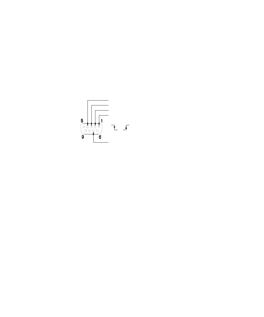
Alarms Connector
or
Alarm 4 Output
Alarm 3 Output
Alarm 2 Output
Alarm 1 Output
Gnd