7Tutorial
272 Keysight 34970A/34972A User’s Guide
Sources of System Cabling Errors
Radio Frequency Interference
Most voltage-measuring instruments can generate false readings in the presence
of large, high-frequency signals. Possible sources of high-frequency signals
include nearby radio and television transmitters, computer monitors, and cellular
telephones. High-frequency energy can also be coupled to the internal DMM on
the system cabling. To reduce the interference, try to minimize the exposure of the
system cabling to high-frequency RF sources.
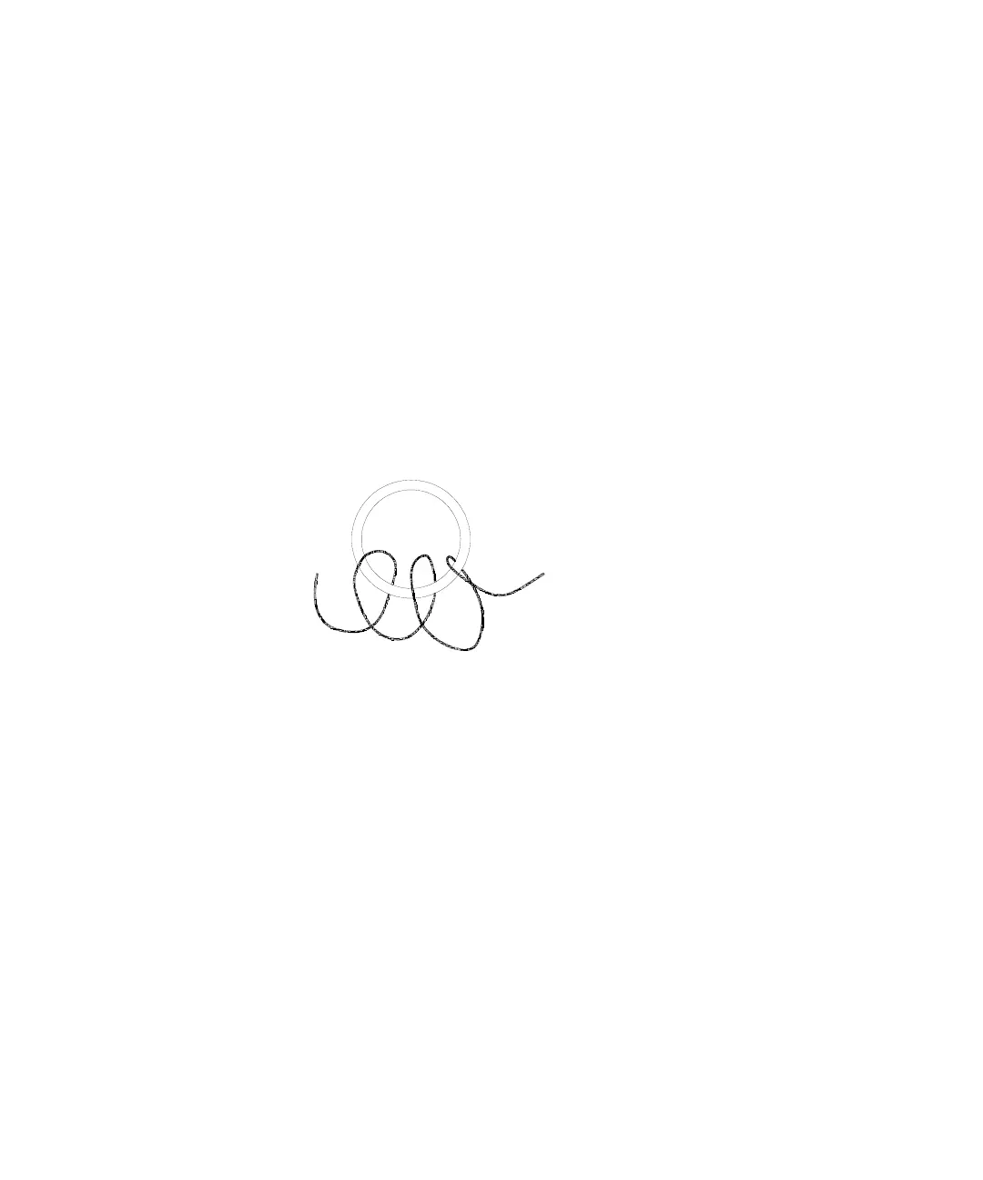
If your application is extremely sensitive to RFI radiated from the instrument, use a
common mode choke in the system cabling as shown below to attenuate
instrument emissions.
Thermal EMF Errors
Thermoelectric voltages are the most common source of error in low-level DC
voltage measurements. Thermoelectric voltages are generated when you make
circuit connections using dissimilar metals at different temperatures. Each
metal-to-metal junction forms a thermocouple, which generates a voltage
proportional to the junction temperature difference. You should take the
necessary precautions to minimize thermocouple voltages and temperature
variations in low-level voltage measurements. The best connections are formed
using copper-to-copper crimped connections. The table below shows common
thermoelectric voltages for connections between dissimilar metals.
Torroid
To Transducers
To Plug-In
Modules