Tutorial 7
Keysight 34970A/34972A User’s Guide 327
RF Signal Multiplexing
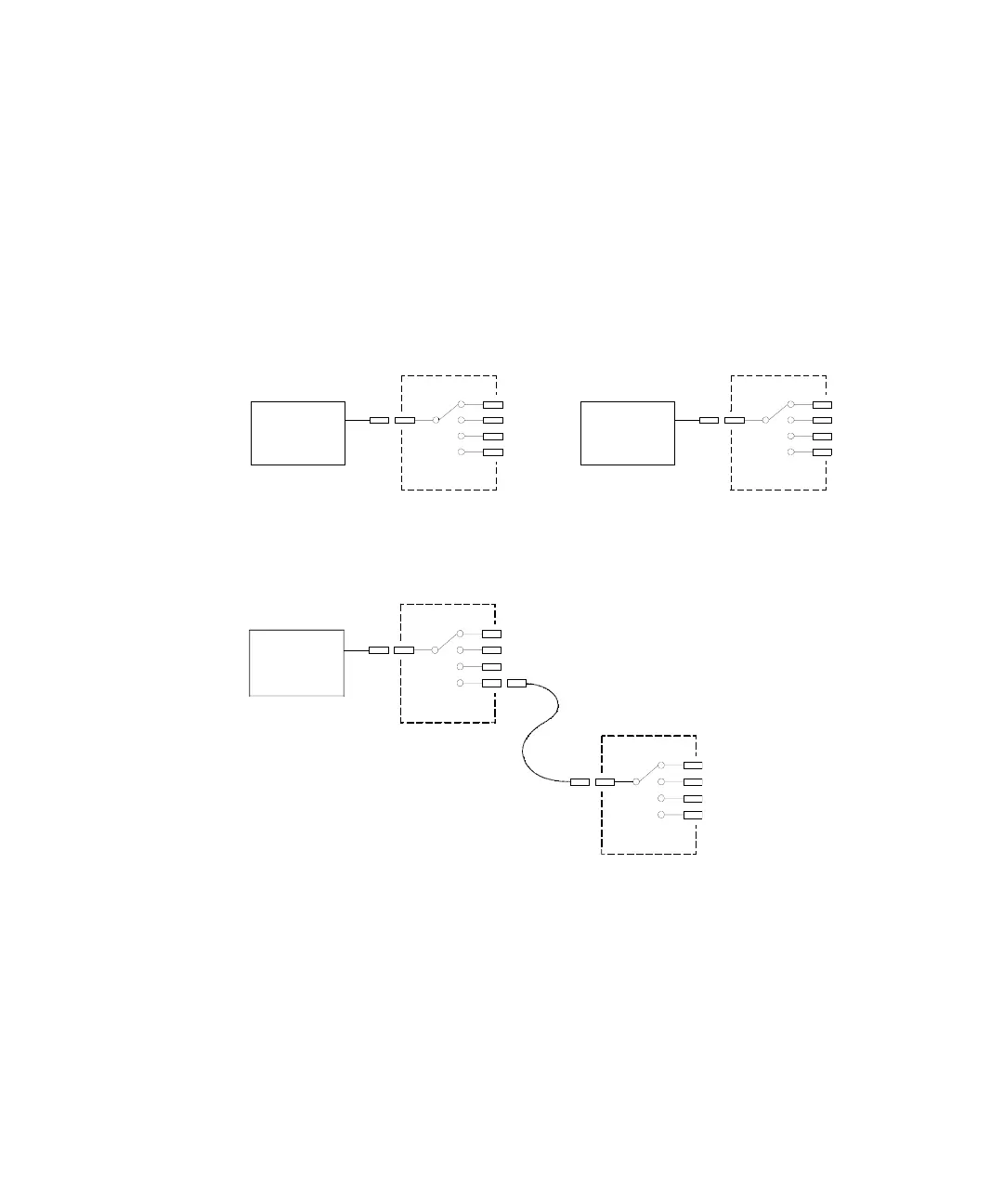
A special type of multiplexer is the RF multiplexer. This type of multiplexer uses
special components to maintain a 50Ω or 75Ω impedance in the signal line being
switched. In a test system, these switches are often used to route a test signal
from a signal source to the device-under-test. The switches are bi-directional. The
diagram below shows two examples of a 4-to-1 channel RF multiplexer in a test
system.
By using patch cables, you can expand RF multiplexers to provide additional test
inputs or outputs. For example, you can combine two 4-to-1 multiplexers to
create a 7-to-1 multiplexer as shown below.
On the 34905A (50Ω) and 34906A (75Ω) RF multiplexers, you can close only one
channel per bank at a time; closing one channel in a bank will open the previously
closed channel. These modules respond only to the CLOSE command (OPEN does
not apply). To open a channel, send the CLOSE command to another channel in
the same bank.
Source 1
Source 4
4 x 1 Multiplexer 4 x 1 Multiplexer
Source 2
Source 3
Signal
Generator
External
Power Meter
Test 1
Test 2
Test 4
Test 3
Test 7
Test 6
Test 5
Patch Cable
Oscilloscope
4 x 1 Multiplexer
4 x 1 Multiplexer