4 Features and Functions
164 Keysight 34970A/34972A User’s Guide
Totalizer Operations
The multifunction module has a 26-bit totalizer which can count TTL pulses at a
100 kHz rate. You can manually read the totalizer count or you can configure a
scan to read the count.
– The totalizer channel is numbered “s03”, where s represents the slot number.
– You can configure the instrument to count on the rising edge or falling edge of
the input signal.
– You can control when the totalizer actually records counts by providing a gate
signal
(G and terminals on the module). A TTL high signal applied to the
“G” terminal enables counting and a low signal disables counting. A TTL low
signal applied to the “ ” terminal enables counting and a high signal disables
counting. The totalizer only counts when both terminals are enabled. You can
use either the G terminal, the terminal, or both. When a gate is not
connected, the gate terminal floats to the enabled state, effectively creating a
“gate always” condition.
– Using the hardware jumper labeled “Totalize Threshold” on the module, you
can control the threshold at which an edge is detected. Move the jumper to the
“AC” position to detect changes through 0 volts. Move the jumper to the “TTL”
position (factory setting) to detect changes through TTL threshold levels.
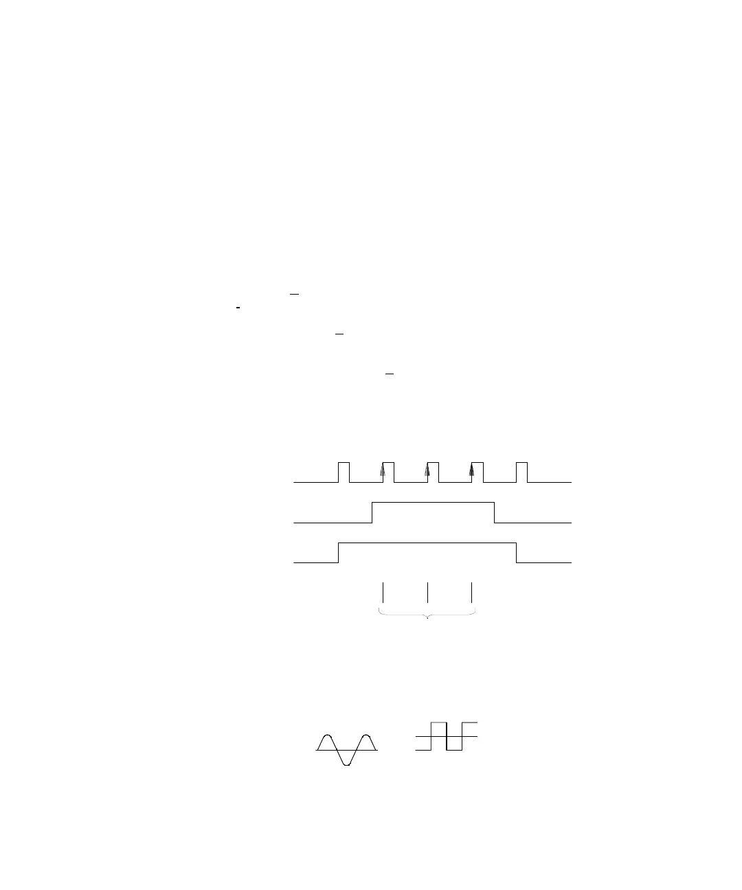
Input Signal
(Rising Edge)
Gate Signal
Totalizer Input
(High True)
Add to Total
2.5 V Threshold (TTL)
0 V Threshold (AC)