53220A/53230A Measurements 3
Keysight 53220A/53230A User’s Guide 105
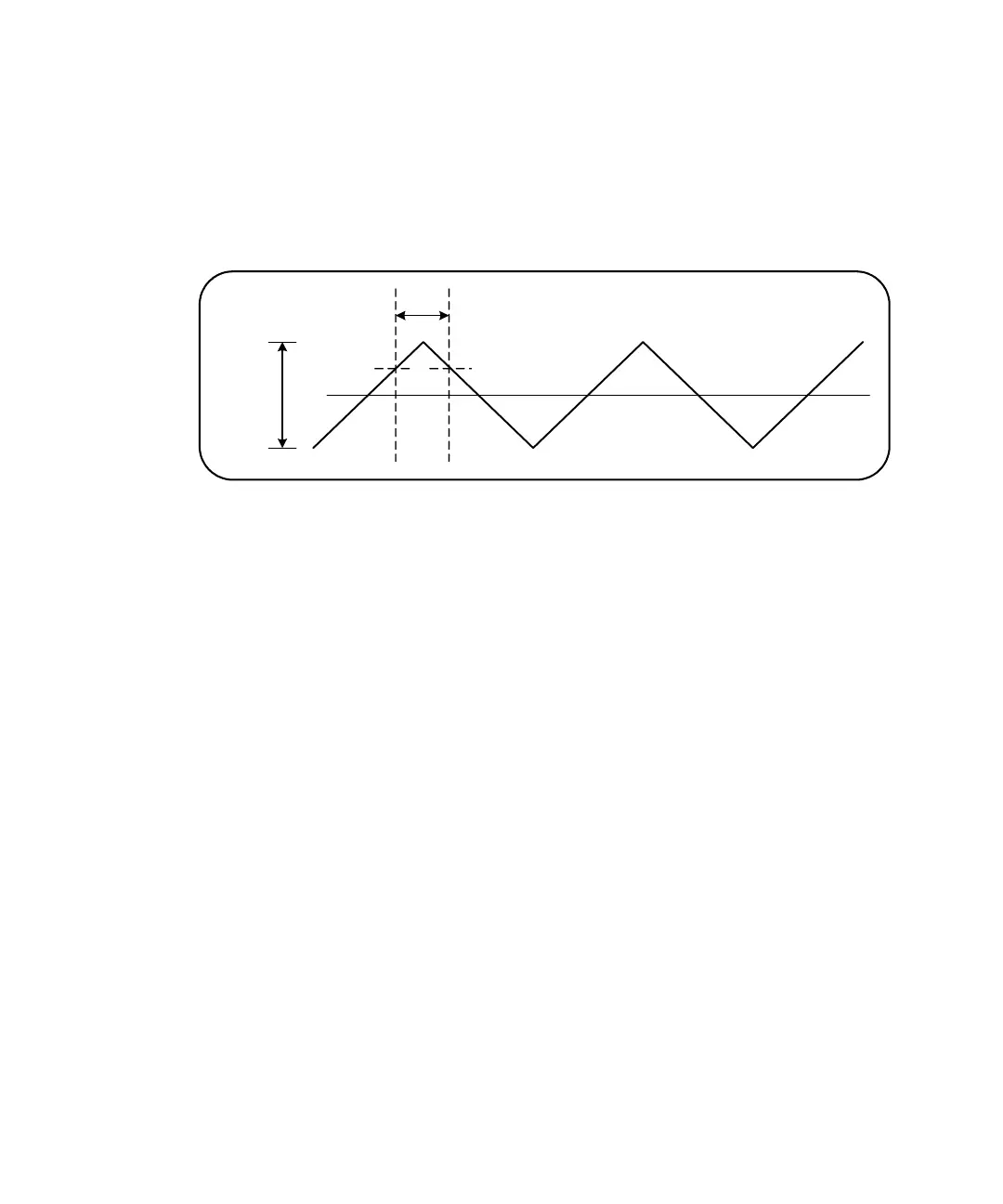
Single-channel time interval measurement
The following example shows a single channel time interval measurement on a
signal with the characteristics shown in Figure 3-7.
Figure 3-7 Single channel time interval measurement.
//configure a time interval measurement on ch.1. Use
//defaults as set by CONFigure except for those set as //shown
*RST // reset to start from known state
CONF:TINT (@1)
INP:COUP AC // set AC coupling
INP:IMP 50 // set input impedance to 50 ohm
INP:LEV1 1.0 // set start threshold to 1V
INP:LEV2 1.0 // set stop threshold to 1V
INP:SLOP1 POS // set start slope to positive (rising)
INP:SLOP2 NEG // set stop slope to negative (falling)
READ? // initiate counter and take reading
Notes
1 Input coupling and impedance are set to assure the intended start and stop
trigger thresholds as the thresholds are specified as absolute values. The
measurement starts on the positive (rising) edge on channel 1, and stops on
the negative (falling) edge.