1 Preparation for Use
24 Keysight 53220A/53230A User’s Guide
Standby power (when enabled) is provided by the line voltage or Battery Option
300 and is used to maintain the temperature of the oven-controlled crystal
oscillator (OCXO) - Option 010. See “Applying Power” in this chapter for more
information.
H. USB ‘Host’ Port - available for transferring measurement data and instrument
configurations between the counter and a USB storage device. The front panel
port is for information transfer only. The rear panel USB port is used for
instrument (I/O) control. Data flow is covered in Chapter 7.
Rear panel
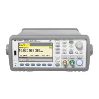
The 53230A rear panel shown in Figure 1-1 includes product Option 201 (parallel
rear panel inputs) and GPIB interface Option 400. The rear panel terminals are
briefly described below.
A. Parallel Rear Panel Inputs - product Options 201 and 202 add parallel inputs
on the rear panel. Note that these ARE NOT separate inputs. Signals on the center
conductor of either panel’s channel BNCs are ALSO present on the opposite
panel’s center conductor. Signal path configuration is covered in Chapter 4.
B. Ext Ref In - is the connector for providing an external reference oscillator
signal. Valid external refererence oscillator (time base) frequencies are 1, 5, and
10 MHz.
Int Ref Out - is the connector for accessing the counter’s internal 10 MHz
reference oscillator. The oscillator signal is a 0.5 Vrms (into 50 Ω) sine wave.
Reference oscillator usage and configuration are covered in Chapter 3.
C. Gate In/Out - is an input for external gate signals, and an output for routing the
counter’s internal gate to other devices. Additional information on this connector
is covered in the section “Enabling Gate Signals on the ‘Gate in/Out’ BNC” in
Chapter 5.
Trig In - is the connector for supplying an external trigger signal to the counter.
Triggering is covered in Chapter 5.
D. USB and LAN - are the standard input/output (I/O) ports. Configuration of
these ports and the GPIB interface is covered in Chapter 2.