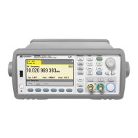
Channel Configuration
Main Measurement Display
Softkey Navigation
Input Settings
: measurement start edge
10% : trigger threshold
AC : input coupling (ac or dc)
1MW : input Impedance (1MW, 50W)
5V : input Range (5V, 50V, 500V)
Probe : probe enabled
BW : bandwidth filter enabled
Channel and Function
Soft Keys
Secondary Measurements
Main Measurement
Data Entry Area
Status Indicators
RMT: remote (LAN, USB, GPIB) operation
ExtRef: external frequency reference
ExtRef : invalid external reference
ExtTrig: external trigger source
Ch. 1 Ch. 2
Ga t e
Battery status:
charge level
black – user disabled
red – software disabled