53220A/53230A Input Signal Conditioning 4
Keysight 53220A/53230A User’s Guide 133
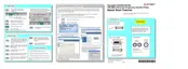
Signal Conditioning Path
Figure 4-1 represents the counter’s signal conditioning path.
Figure 4-1 53220A/53230A input signal conditioning.
Table 4-1 is a summary of power-on/reset values for the signal conditioning
parameters.
Threshold Level
and Sensitivity
Input
AC Coupling
trigger / gating
INPut{1|2}:COUPling
INPut{1|2}:IMPedance
INPut{1|2}:PROTection?
INPut{1|2}:PROTection:CLEar
INPut{1|2}:LEVel{1|2}
SYSTem:ALEVel:FREQuency
INPut{1|2}:LEVel:AUTO
INPut{1|2}:LEVel{1|2}:RELative
INPut3:BURSt:LEVel
INPut{1|2}:NREJect
INPut{1|2}:SLOPe{1|2}
Selectable
100 kHz
Low-Pass Filter
INPut{1|2}:FILTer
Range
Selection
INPut{1|2}:RANGe
INPut{1|2}:PROBe
Auto
Cal
Buffer
DC Coupling
50W
1MW
Input
Protection