4 53220A/53230A Input Signal Conditioning
138 Keysight 53220A/53230A User’s Guide
AC coupling removes the signal’s DC content and centers the signal at 0 V. The
measurable frequency range (channels 1 and 2) with AC coupling is:
– AC = 10 Hz - 350 MHz
– DC = 1 mHz - 350 MHz
DC coupling extends the frequency range across the full bandwidth of the
instrument (1 mHz - 350 MHz). CONFigure and MEASure do not change the
coupling setting. Following a reset (*RST) or front panel preset (Preset), the
coupling is set to AC.
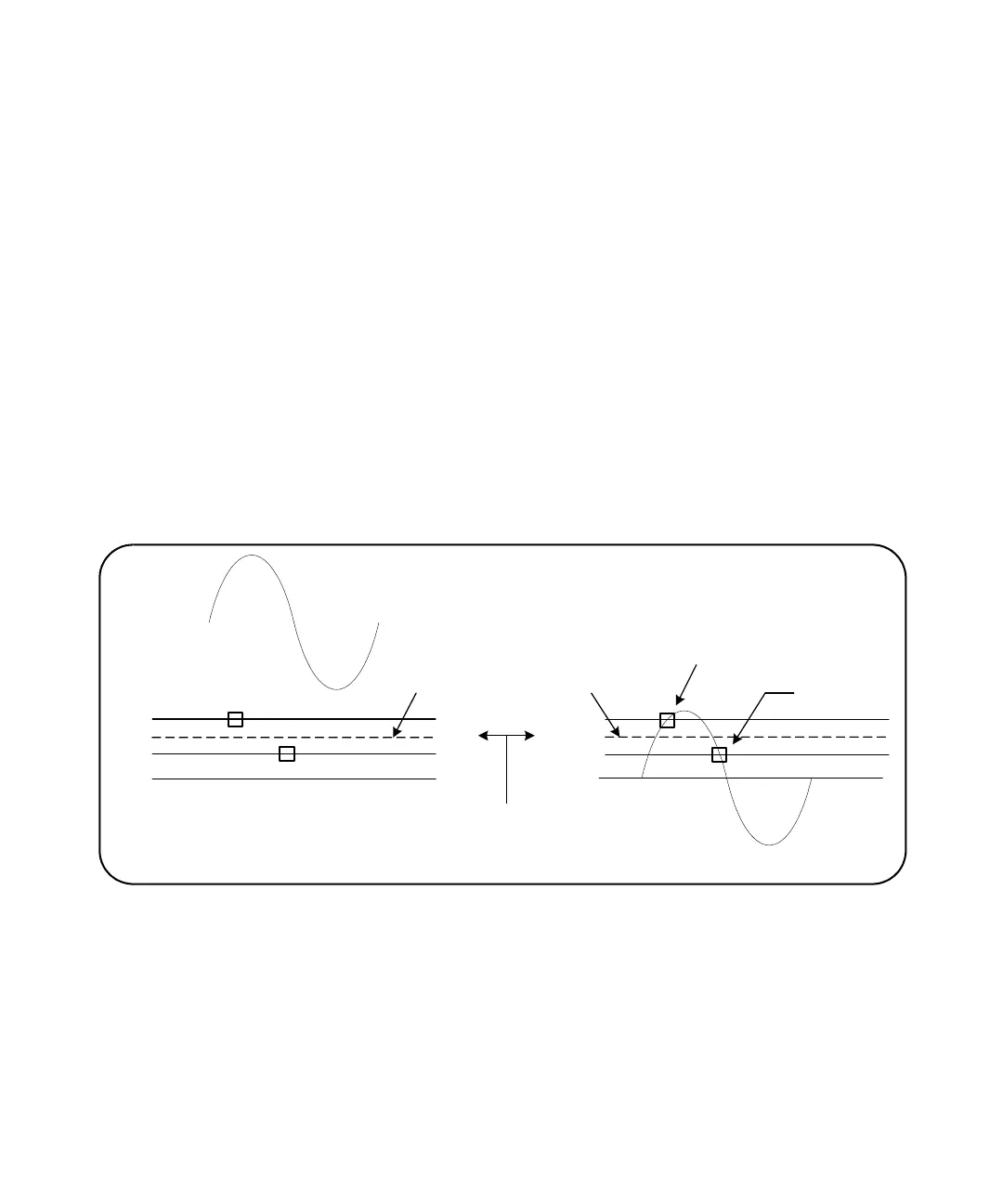
When selecting AC or DC coupling, the amplitude of the input signal must also be
considered. DC coupling is applicable for most measurements, especially those
requiring a specific trigger level. Rather than reducing the signal amplitude by
changing the counter range, AC coupling can be used to bring the signal in
contact with the hysteresis window defined by the trigger level. This is
represented in Figure 4-2 (also see “Threshold level and sensitivity”).
Figure 4-2 Using AC coupling to reach trigger points.
Settling time between dc and ac coupling
There is an inherent settling time when changing from DC to AC coupling. As a
measure of this time, a signal with a 5V DC component (DC coupled) will typically
center around 0V (AC coupled) in one second.
V
U
V
L
V
C
V
U
V
L
0V
AC coupling
0V
DC coupling
V
C
programmed trigger level
}
}
Hysteresis window
trigger point
reset point
input signal with DC offset