53220A/53230A Input Signal Conditioning 4
Keysight 53220A/53230A User’s Guide 141
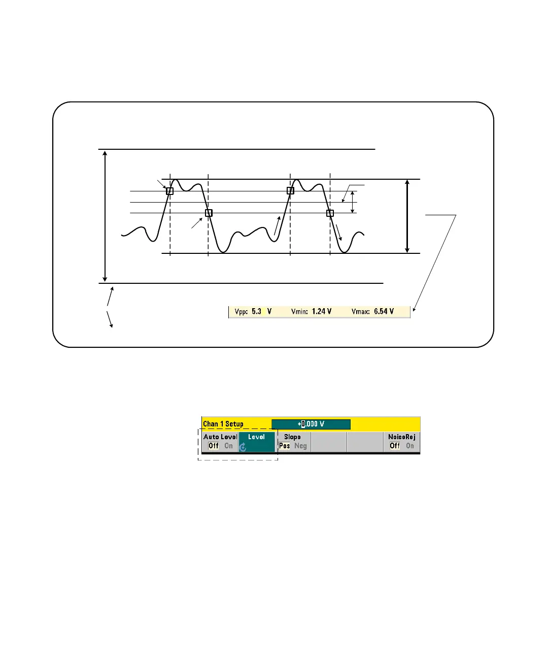
Figure 4-4 Input signal threshold level and sensitivity.
Specifying an absolute threshold level
The input threshold level can be specified as an absolute value. An absolute level
is set with the command:
INPut[{1|2}]:LEVel[{1|2}][:ABSolute] {<volts>|MINimum|
MAXimum|DEFault}
INPut[{1|2}]:LEVel[{1|2}][:ABSolute]? [{MINimum|MAXimum|
DEFault}] (query form)
V
U
V
L
V
C
signal operating range
trigger point
reset point
Hysteresis band
(p-p sensitivity)
threshold level
INPut{1|2}:SLOPe{1|2}
INPut{1|2}:LEVel{1|2}
SYSTem:ALEVel:FREQuency
INPut{1|2}:LEVel{1|2}:AUTO
INPut{1|2}:LEVel{1|2}:RELative
INPut3:BURSt:LEVel
INPut{1|2}:NREJect
positive slope
negative slope
dynamic range
front panel dynamic range indicator
INPut{1|2}:LEVel:MAXimum?
INPut{1|2}:LEVel:MINimum?
INPut{1|2}:LEVel:PTPeak?
0