4 53220A/53230A Input Signal Conditioning
150 Keysight 53220A/53230A User’s Guide
Time interval errors Using noise rejection with time interval measurements
results in time interval errors due to errors in setting the threshold level and the
effects of hysteresis on the trigger and reset points (Figure 4-4). These errors are
dependent on the input signal slew rate at each trigger point.
Noise rejection example
//period measurement of expected 10 MHz signal,
//use channel 1
CONF:PER 0.1E-6,.001,(@1)
INP:IMP 1.0E6 //set impedance to 1 Mohm
INP:RANG 50 //set range to 50
INP:COUP AC //set AC coupling
INP:LEV 3 //set 3V threshold level (absolute)
INP:NREJ ON //enable noise rejection
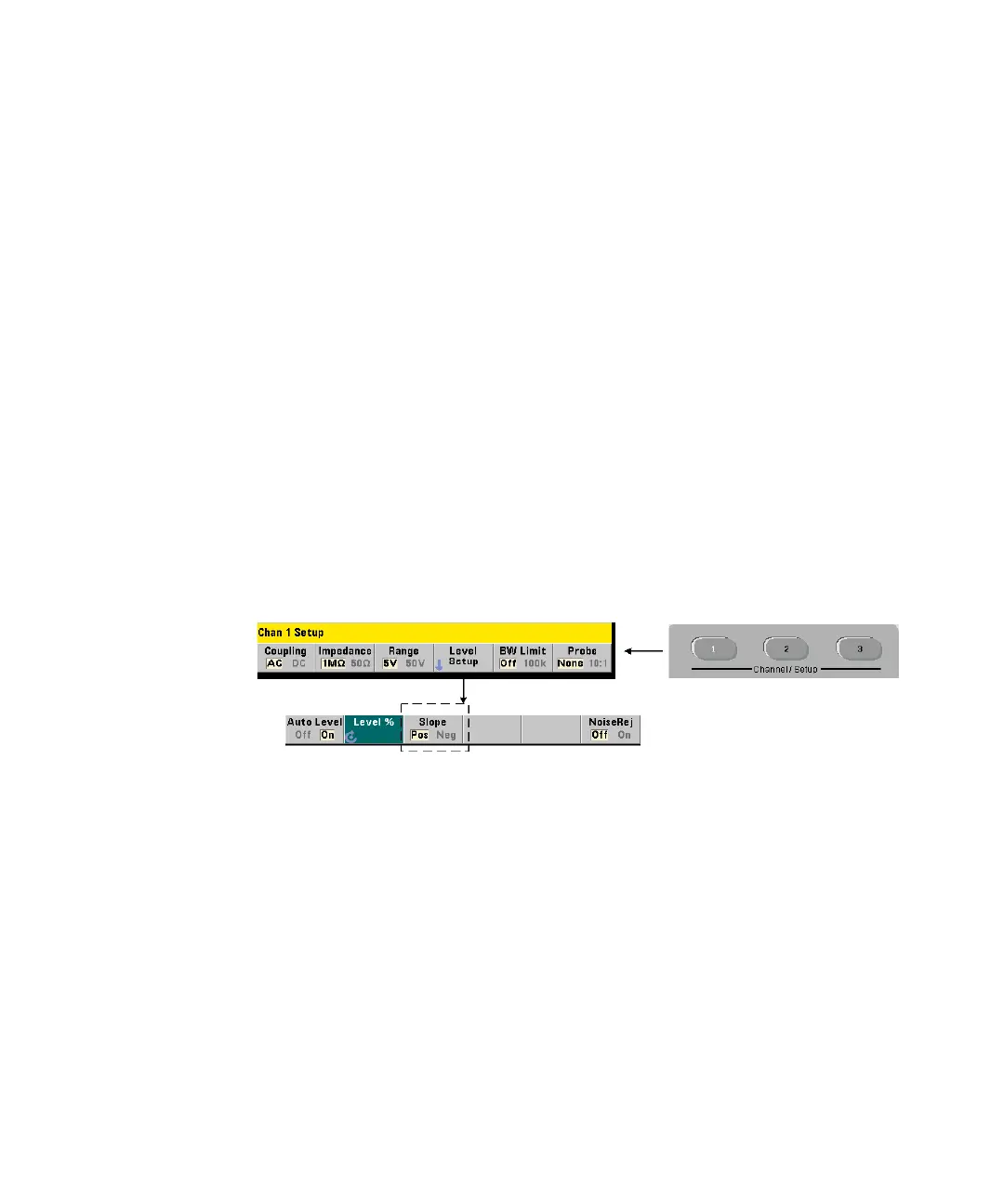
Threshold slope
The slope (edge) of the input signal on which the threshold level occurs is
specified with the command:
INPut[{1|2}]:SLOPe[{1|2}] {POSitive|NEGative}
INPut[{1|2}]:SLOPe{1|2}]? (query form)
POSitive - the trigger point occurs on the positive (rising) edge. The reset point
occurs on the negative (falling) edge (Figure 4-4).
NEGative - the trigger point occurs on the negative edge, with the reset point
occurring on the positive edge.
The slope setting does not apply to pulse width, duty cycle, or rise/fall time
measurements (i.e. measurements with pre-defined slopes).