Chapter 1: Installation and wiring
14 P/N 3102351-EN • REV 005 • ISS 28DEC18
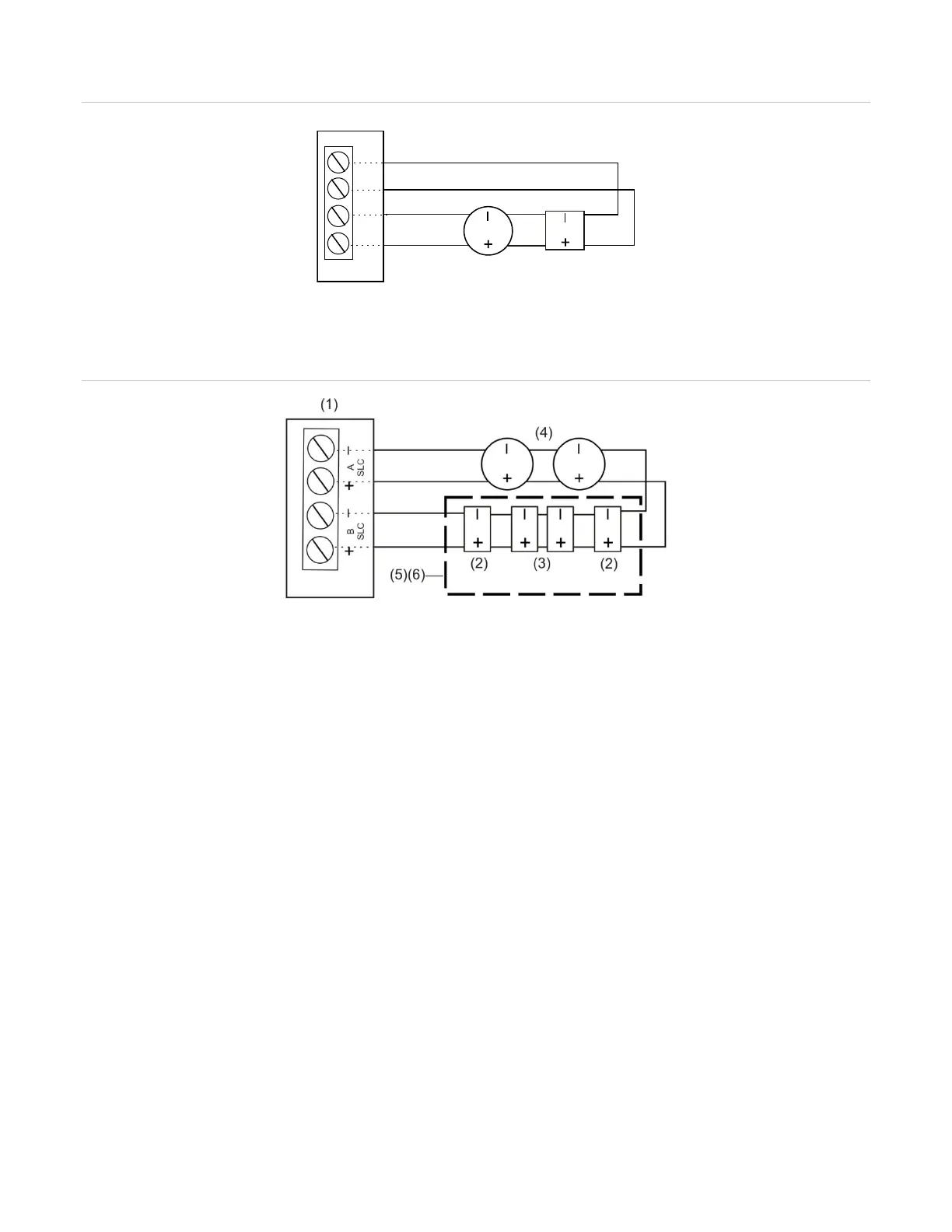
Figure 16: Class A wiring [1]
Figure 17: Class X wiring [2]
2) Isolator module
SLC devices
(4) SLC devices with an isolator base
(5) UL/ULC listed enclosure
(6) For Class X wiring, un-
isolated devices must be
mounted in a cabinet with isolators on the incoming
and outgoing wiring.
Notes for Figure 16 and Figure 17.
[1] For Class A wiring, isolator modules and isolator detector bases are required to prevent wire-to-wire shorts on
the signaling line circuit wiring from adversely affecting other segments of the loop. Do not install more than 50
addressable devices between isolators, per NFPA 72.
[2] For Class X wiring, isolator modules and isolator detector bases are required to prevent wire-to-wire shorts on
the signaling line circuit wiring from adversely affecting any devices of the loop.
Loop card LEDs
There are two LEDs on the card for each SLC that indicate SLC communication status. See
Figure 18 and Figure 19 for LED functions and location.
The installation location of the card on the panel determines what panel SLC the LEDs are
associated with for VS4 that support dual SLC cards and provide two installation locations.
See Figure 20.