2J5
2-3-2
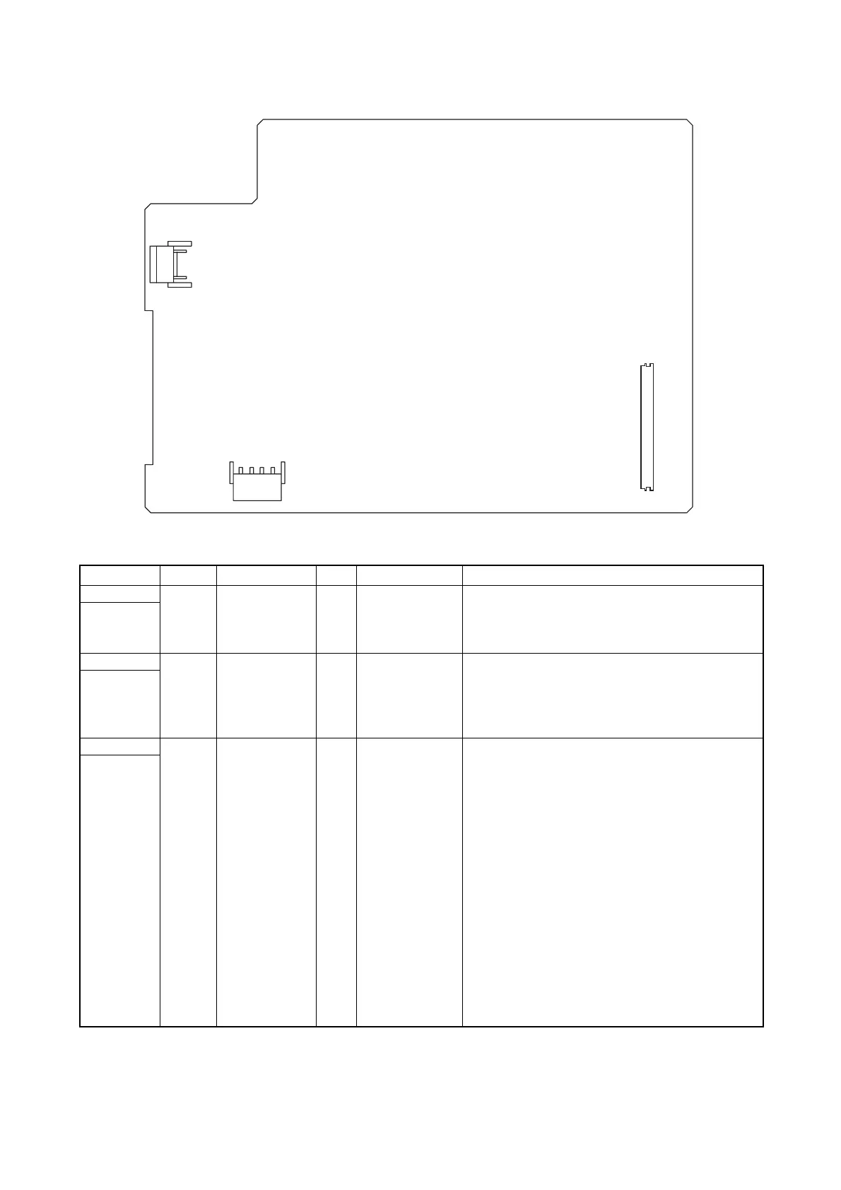
Figure 2-3-2Power source unit silk-screen diagram
Connector Pin No. Signal I/O Voltage Description
YC101 1 LIVE I 220 - 240 V AC AC power input
Connected
to the AC
inlet
2 NEUTRAL I 220 - 240 V AC AC power input
YC102 1 COMMON1 O 220 - 240 V AC Fuser heater lamp M
Connected
to the heater
lamp M and
S
2 N.C. - - Not used
3 LIVE O 220 - 240 V AC
4 N.C. - - Not used
5 COMMON2 O 220 - 240 V AC Fuser heater lamp S
YC103 1 +5V1 O 5 V DC 5 V DC power source
Connected
to the con-
nect-L PWB
2 +5V1 O 5 V DC 5 V DC power source
3 +5V1 O 5 V DC 5 V DC power source
4 +24V1 O 24 V DC 24 V DC power source
5 N.C. - - Not used
6 HANDSN O 0/5 V DC MP tray paper feed sensor: On/Off
7 HEATONN2 I 0/5 V DC Fuser heater lamp S: On/Off
8 HEATONN1 I 0/5 V DC Fuser heater lamp M: On/Off
9 ZCROSS O 0/5 V DC (pulse) Zero cross signal
10 SWSLEEPN I 0/5 V DC Sleep mode: On/Off
11 +24V2 O 24 V DC 24 V DC power source (via interlock switch)
12 GND - - Ground
13 GND - - Ground
14 GND - - Ground
15 GND - - Ground
16 +24V2 O 24 V DC 24 V DC power source (via interlock switch)
17 +24V2 O 24 V DC 24 V DC power source (via interlock switch)
YC101
YC102
1
1
YC103
1
 Loading...