2J5
1-5-22
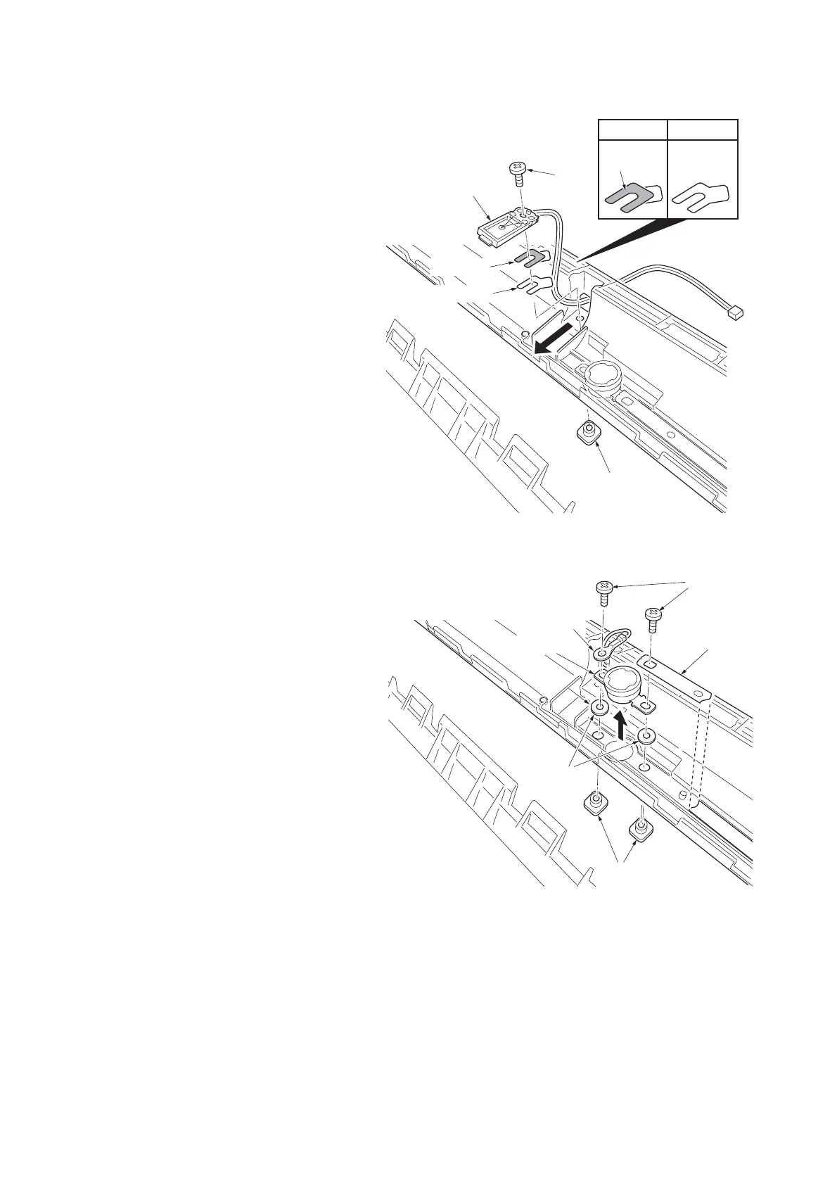
8. Remove the screw (nut) and then remove
the fuser thermistor M.
NOTE:
Set spacer A so that its insulating sheet
faces the fuser thermistor.
The number of spacer Bs differs depending
on the fuser unit.
Figure 1-5-30
9. Remove two screws (nuts) and then remove
the terminal and cord plate.
10. Remove the thermal cutout.
11. Check or replace the fuser thermistor S and
M and thermal cutout and refit all the
removed parts.
Figure 1-5-31
Nut
Screw
Fuser thermistor M
Spacer A
Spacer A
Spacer B
Spacer B
Insulating
sheet
Cord plate
Terminal
Nuts
Screw
Spacers
Thermal cutout
 Loading...