Rigging dV-DOSC Under dV-SUB (3+1 configuration)
When rigging small configurations of dV-DOSC under a single dV-SUB (e.g., 1 dV-SUB with 3 dV-
DOSC underneath), it is possible to fly the system in the same manner as dV-DOSC standalone, i.e.,
assemble the enclosures while they are face down on their dollies and fly the system as a whole.
Note: For larger configurations with more than 3 dV-DOSC flown under multiple dV-SUBs, see the following
section for rigging procedures.
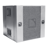
To fly the system, the dV-SUB enclosure is located at the rigging location (face down on it's dolley)
and four dV-ANGLESD are pre-attached to the dV-SUB using 4 x dV-PIN25 (in preparation for
attaching dV-BUMP). The ''fat'' part of the dV-ANGLESD is oriented towards the center of dV-SUB on
both sides.
Note: Since there are no stacking runners on the top of dV-SUB, it is possible to select the stacked hole
position on the dV-SUB end of dV-ANGLESD.
Place the dV-BUMP into position on dV-SUB and secure using 4 x dV-PIN25. The dV-BUMP is
positioned so that the rear extension bar receptacle is oriented upwards. If desired, attach the
extension bar to dV-BUMP using an 18 mm shackle at pick point hole #8 on the central spreader bar
section of dV-BUMP. The extension bar allows the use of two motors for tilt adjustment or single
point hangs from the 8 additional points available on the extension bar. If the extension bar is not
used, 8 pick point positions are available on the central spreader bar section of dV-BUMP for single
point hangs.
Pre-attach 2 x dV-ANGLESD at the (bottom) front and 2 x dV-ANGLESDP at the (bottom) rear of the
dV-SUB using 4 x dV-PIN25. Recall that the outermost holes on these angle bars are used for flown
applications (to provide clearance for the stacking runners) and the ''fat'' part of the angle bars is
oriented towards the center of dV-SUB in order to mate properly with the dV-DOSC rigging panels.
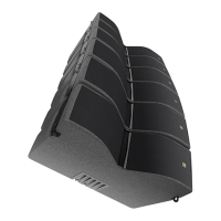
Line up the 3 dV-DOSC enclosures in their flight case (3 per case) at the rigging location. Physically
connect the fronts of all dV-DOSC enclosures by attaching the front points using pairs of dV-PIN25.
The entire assembly is then physically linked, similar to how V-DOSC is attached using rotating legs
and U-pins (except the attachment points are at the front in this case).
Referring to the angle values that were pre-calculated for each enclosure using ARRAY 2004 or
SOUNDVISION, pre-attach pairs of dV-ANGLE bars at the rear of all dV-DOSC enclosures of the
array (while they are still face down in their flight cases). Remember to keep the ball/tab end up as a
reference and be careful to select the correct angle for each enclosure (generally, it is better if one
person performs this operation to avoid mistakes).
Connect the rears of the 3 dV-DOSC enclosures (while they are still face down in their flight cases) by
pulling the cabinets together at the rear and inserting dV-PIN25. This operation is facilitated by the
fact that all fronts are pinned together and can pivot, plus all rear angles were pre-attached in the
previous step.
Pre-connect the rear point for the first dV-DOSC to the dV-SUB, i.e., use 2 x dV-PIN25 to secure dV-
DOSC to the dV-ANGLESDP that was pre-attached at the (bottom) rear of dV-SUB
Note: Selecting the 0 degree angle on dV-ANGLESDP (between the rear of the top dV-DOSC enclosure and
dV-SUB) is necessary to compensate for the 3.75 degree trapezoidal angle of dV-DOSC versus the actual
site angle of the enclosure which is perpendicular to the front. Selecting the 0 degree angle allows focus to
be verified visually or with a laser attached to the bottom of dV-SUB since this will then be referenced to the
actual site angle of the top dV-DOSC enclosure.
Connect all enclosures to the AMP RACKS using appropriate cables and adaptors (SP and DO2W or
DO plus DOFILL) and SP.7 jumpers between enclosures for parallel operation. Long cable runs should
be dressed and tied off to dV-BUMP for strain relief. Be careful not to connect more than 3 dV-DOSC
enclosures in parallel.
Conduct a final inspection to make sure all cabling is correct, proper inter-enclosure angles have been
selected and that all dV-PINs are in place and securely seated.