dV-DOSC dV-SUB Manual V3.0 June 2005 55
General Guidelines Regarding System Protection
Standard limiter thresholds for dV-DOSC are based on twice the RMS power handling for each
section and set at +7 dBu (100 Hz HPF) or +5 dBu (80 Hz HPF) for the low section and +1 dBu for
the high section. For additional protection, L-ACOUSTICS LA24a and LA48a output power can be
matched to dV-DOSC power handling capabilities using MLS switches (refer to tables 3, 4 and 5 for
recommended settings).
L-ACOUSTICS recommends that LA power amplifier clip limiters are engaged at all times and power
amplifiers must have 32 dB gain.
Limiter thresholds are user accessible and exact settings will depend on individual engineer
preferences and the type of music or application which, in turn, determines how hard the dV-DOSC
system is being operated. When additional protection is desirable, limiter thresholds can be lowered
to match the rms power handling for individual sections according to the tables below:
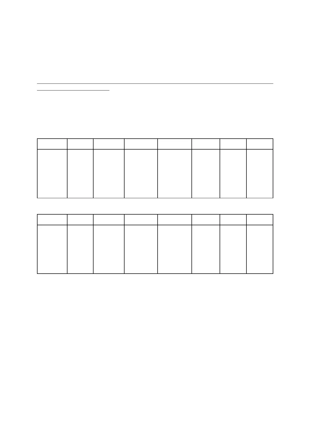
Table 15: Recommended Limiter Threshold Settings
STANDARD LIMITER THRESHOLDS CALIBRATED TO 2 x RMS POWER HANDLING
ENCLOSURE NOM LOAD RMS POWER PEAK POWER REC'D POWER EQUIV Vrms dBu EQUIV
LIMITER
MODEL (ohms) (W) (W) (W) (volts) (32 dB gain)
SETTING *
SB218 411004400
2200
93.8
9.62 9 dBu
dV-SUB 2.7 1200 4800
2400
80.5
8.29 8 dBu
dV-DOSC LO 8 380 1520
760
78.0
8.01 7 dBu
dV-DOSC HI 8 66 264
132
32.5
0.41 1 dBu
* AMP CLIP IS AT 9.5 dBu
LIMITER THRESHOLDS CALIBRATED TO RMS POWER HANDLING
ENCLOSURE NOM LOAD RMS POWER PEAK POWER RMS POWER EQUIV Vrms dBu EQUIV
LIMITER
MODEL (ohms) (W) (W) (W) (volts) (32 dB gain)
SETTING
SB218 411004400
1100
66.3
6.61 6 dBu
dV-SUB 2.7 1200 4800
1200
56.9
5.28 5 dBu
dV-DOSC LO 8 380 1520
380
55.1
5.00 5 dBu
dV-DOSC HI 8 66 264
66
23.0
-2.60 -2 dBU
NOTE: The LA48a has relatively low input sensitivity (9.5 dBu) and, in practice, it can be necessary to
equally scale up the individual crossover channel output gains in order to have sufficient drive
capability (note: this has been done for Version 7 preset library release). It is far better to use the
output drive capability of the DSP digital-to-analog converters (DACs) and analog output section
rather than overdrive the input analog-to-digital converters (ADCs) so do not be afraid to increase the
channel output gains uniformly in order to achieve a comfortable gain structure. Whether this is
necessary will also depend on how ''hot or cold'' the FOH mix engineer likes to run his console. When
in doubt, disconnect all loudspeaker cables and run pink noise from the console at nominal level
through the crossover to the power amplifiers and examine crossover input/output levels, crossover
limiter indicators and amplifier clip indicators to verify system protection and gain structure.