dV-DOSC dV-SUB Manual V3.0 June 2005 61
2.2 WAVEFRONT SCULPTURE IN THE VERTICAL PLANE
Flat dV-DOSC Array
Flying or stacking dV-DOSC with 0 degree angles between all enclosures produces a flat array that
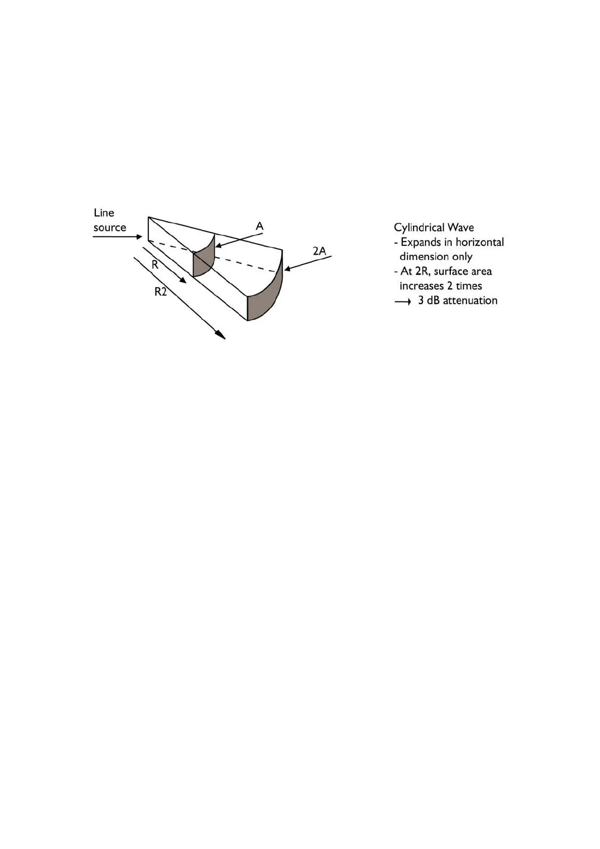
behaves acoustically as a continuous, isophasic line source that radiates a cylindrical wavefront. The
cylindrical wavefront expands in the horizontal dimension only and is defined by the section of a
vertical cylinder over a given distance. The height of this section corresponds to the height of the
array (defined by the top of the upper enclosure and the bottom of the lowest enclosure) and the
coverage angle corresponds to the -6 dB horizontal coverage angle of dV-DOSC (try to visualize a
120° cheese wedge or a piece of cake…)
According to Fresnel analysis, a cylindrical wavefront is radiated by a line source array over a certain
distance and then transforms into a spherical wavefront. In cylindrical mode, the wavefront expands
linearly with distance in the horizontal plane only, thus producing only 3 dB of attenuation when
doubling the distance. In spherical mode, the wavefront expands in two dimensions, thus producing a
SPL attenuation of 6 dB with doubling of distance. The boundary between cylindrical and spherical
wavefront propagation regions depends on the frequency and length of the line source.
Since dV-DOSC is, in essence, more efficient at projecting HF energy than LF, the net result is that for
large distances, the tonal balance is progressively tilted by a HF enhancement. For longer throw
distances, this tilt in tonal balance is offset by air absorption in open air situations and by both building
material absorption and air absorption indoors, resulting in spectrally-balanced sound over the largest
area possible. This is an important benefit of dV-DOSC and WST since both SPL and tonal balance are
more even with distance.
Since the flat array configuration maximizes energy and intelligibility with distance, it should be used
for long throw applications or in reverberant rooms. It is also common to use a flat array section at
the top of a variable curvature array for improved throw in arena and stadium installations.
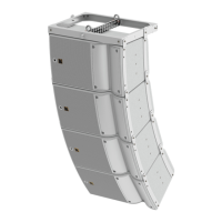
Convex Curvature dV-DOSC Array
A convex or positive curvature dV-DOSC array (stacked or flown) is obtained by using dV-ANGLE P1
or P2 bars to provide the desired angle between each enclosure. If the angle between two adjacent
dV-DOSC enclosures is less than 7.5°, WST criteria are satisfied and the array behaves like a
continuous, curved radiating ribbon. If the angle between enclosures exceeds 7.5°, WST criteria are
no longer valid over the full audio frequency range. Practically, a larger angle produces neither
desirable nor predictable results - enclosures radiate individually and the benefits of collective coupling
are lost. That is why dV-ANGLE bars and the trapezoidal shape of the dV-DOSC enclosure itself
allows up to 7.5° maximum angle between enclosures.
There are two types of convex curvature V-DOSC array: constant curvature and variable curvature.
For the first case, the angle between all adjacent enclosures is constant while for the second case, it
varies within the defined range of 0° to 7.5°.