dV-DOSC dV-SUB Manual V3.0 June 2005 89
3.4.4 Time Alignment: Flown/Ground Stacked Subwoofers
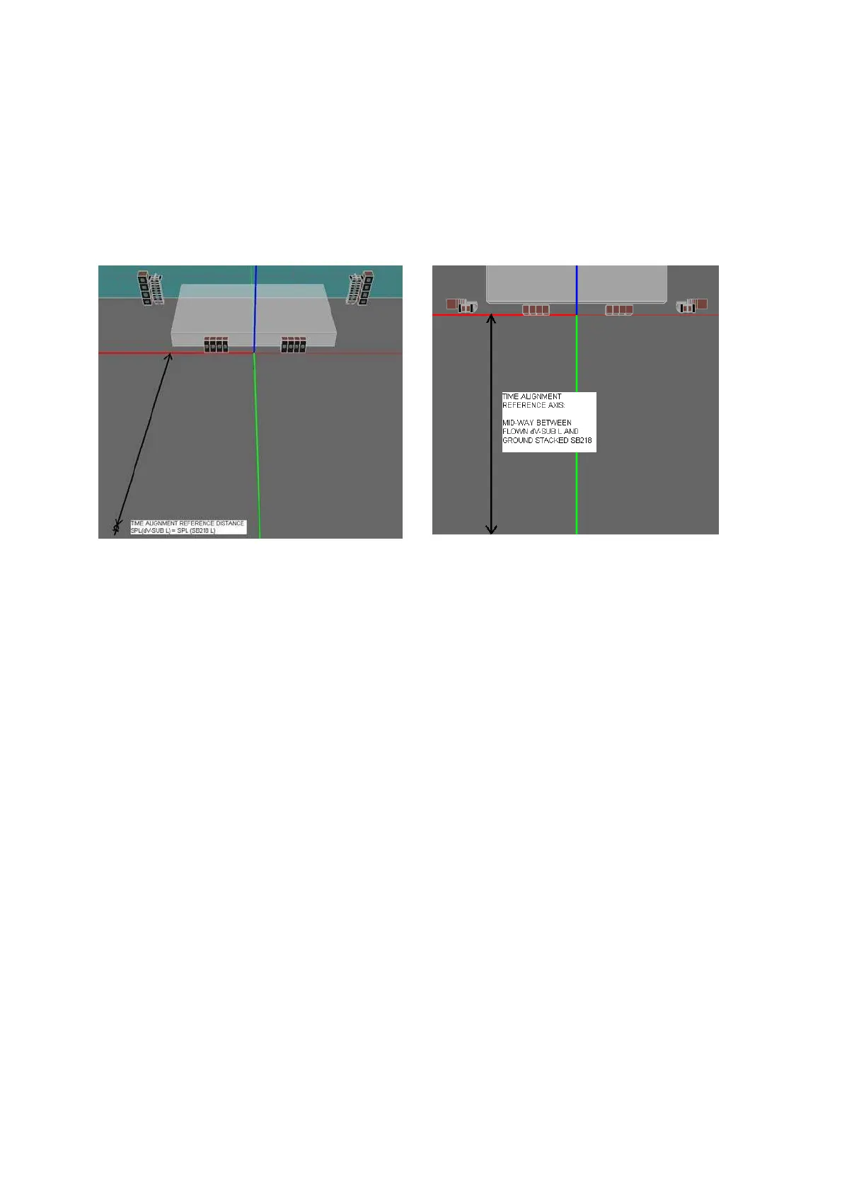
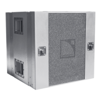
As seen in Fig. 64, selection of the time alignment reference location in the vertical plane is always a
compromise since the geometric path difference varies with position (note: this also occurs in the
horizontal plane and time alignment must be considered in 3D). Time aligning at a distance where the
SPL from ground stacked subwoofers equals the SPL from flown dV-SUBs is recommended as an
optimum compromise (for time alignment in the vertical plane). Horizontally, the reference position
should be mid-way between flown dV-SUB and ground stacked subwoofer arrays. Time aligning in the
middle is not recommended in order to help reduce centre build up and one side should be time
aligned at a time (FOH L as shown in Fig 68).
Figure 68: Recommended time alignment reference location for flown dV-SUB, ground stacked L/R subwoofers
For ground stacked LCR subwoofer arrays (as shown in Fig. 67d), it is recommended that the L
subwoofer array is delayed with respect C array with the measurement microphone on axis to the L
array. Following this, the flown dV-SUB/dV-DOSC array should be time aligned with respect to the L
array using the technique shown in Figure 68.
3.4.5 Preset Selection: Flown/Ground Stacked Subwoofers
For 4-way mode operation, two types of presets are available – INFRA and X. Separate processing is
provided for flown versus ground stacked subwoofers and presets have the following output channel
assignments:
Output 1 SB118 or SB218 ground stacked (input A)
Output 2 dV-SUB flown (input A)
Output 3 dV-DOSC low section (input A)
Output 4 dV-DOSC high section (input A)
Output 5 fullrange (input A)
Output 6 SB118 or SB218 ground stacked (input B)
Note: For all 4-way mode presets, output 6 can be used for auxiliary sub drive via input B.
Note: The crossover frequency between the flown dV-SUB and dV-DOSC low section is 120 Hz to optimize
the power bandwidth for both sections for all 4-way presets.
For INFRA presets, there is a 60 Hz crossover point between SB118 or SB218 subwoofers and dV-
SUB. Complementary 60 Hz crossover filtering helps to avoid phase problems due to overlapping sub
and dV-SUB operating bandwidths so that subwoofers can be operated with positive polarity whether
the system is driven in 4-way mode or with aux sub drive. An additional benefit of the INFRA preset is
that time alignment is more forgiving for a greater part of the audience (due to the longer wavelengths
at 60 Hz) and, subjectively, the subs become more of a delocalized effect due to the lower crossover
point.
For X presets, the dV-SUB operating bandwidth is extended down to 30 Hz and SB118 or SB218
subwoofers are operated from 26-80 Hz with negative polarity (to account for the overlap in sub/low