dV-DOSC dV-SUB Manual V3.0 June 2005 79
Rigging Guidelines
The rigging system is rated for a maximum of 24 dV-DOSC enclosures without the
extension bar and 12 dV-DOSC enclosures with the extension bar
When simulating system coverage using ARRAY2004 or SOUNDVISION, the goal is to select dV-
DOSC inter-enclosure angles so that equal spacing is obtained between enclosure site angle impacts
over the audience geometry (WST Condition 4). Particular attention should be paid to the height at
which the array is flown when predicting the vertical coverage in ARRAY2004 or SOUNDVISION.
Typically, system trim height should be selected to provide a 4:1 ratio between the throw distances to
the furthest and closest members of the audience.
Inter-enclosure angles should not be selected by considering the on-axis cutview only – always
consider audience coverage off the main axis, especially from 50° to 60° on the offstage side. It is
important to check that you are not lacking in offstage coverage and require additional fill systems (see
Multiple Arrays). For improved offstage coverage in arenas, it is best to have the system flown so that
the bumper elevation is at the same height as the highest audience elevation and the top dV-DOSC
enclosure has a zero degree site angle. Conversely, for the hybrid flown/stacked configuration (theatre
sound reinforcement), the trim height of the flown system should be selected so that the bottom dV-
DOSC cabinet has a zero degree site angle and is at the same height as the listening level for the first
row of the balcony audience. This helps avoid reflections from the balcony face while providing more
even off-axis coverage for the first row of the balcony.
It is also common to have two sections of the audience area that have different slopes, for example,
the transition between floor level and the tribune gradient in arenas. In this case, coverage of the areas
at the transition between the two slopes should be examined carefully and angles selected accordingly.
Finally, to effectively complete any dV-DOSC installation - stacked or flown - during the actual
installation, it is important to verify that the parameters calculated in ARRAY 2004 or SOUNDVISION
have been implemented correctly. Tools that are useful for this purpose are described in Chapter 5.4.
Detailed rigging and system focussing procedures are described in Section 4.2.
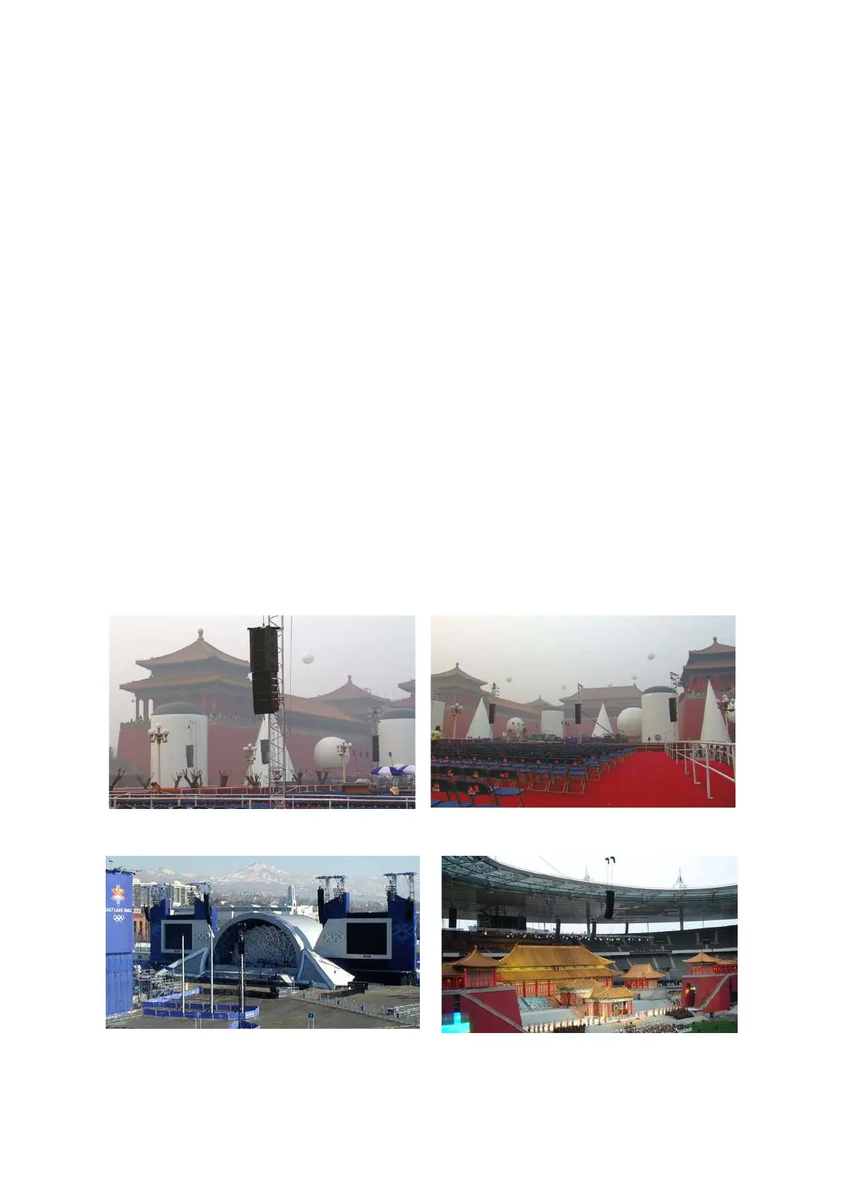
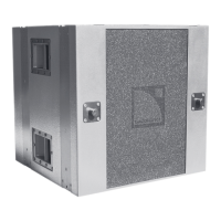
Figure 58a: Flown dV-DOSC + dV-SUB arrays for large format 5.1 sound reinforcement
(Jean Michel Jarre 2005 Beijing, sound designer: C. Dupin)
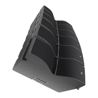
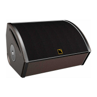
Figure 58b: Flown dV-DOSC delay positions (2002 Olympics - Salt Lake City, Turandot Stade de France 2005)