dV-DOSC dV-SUB Manual V3.0 June 2005 44
1.10 COMB CONNECTORS
COMB connectors are used in conjunction with L-ACOUSTICS signal distribution panels (CO6,
CO24, MD24) to route desired signal lines from the 19-pin CA-COM input connectors on PADO2a
or PADO4a amplifier rack panels to the appropriate amplifier inputs. Amplifier racks can be
conveniently reconfigured without rewiring internally - simply by changing the COMB connector.
COMB connectors for use with dV-DOSC (4-way+2 or 5-way+1 format presets) are:
DSUB = SUB (signal line 1 for SB118 or SB218)
D3WAY = 3-WAY (signal lines 2/3/4 for dV-SUB/dV-DOSC low/dV-DOSC high)
D2WAY = 2-WAY (signal lines 5/6 for 2-way fill low/high, 4+2 presets only)
Additional COMB connectors are available for use with 2-way or 3-way stereo format presets are:
D2WA = 2W(A) (signal lines 2/3 for 2-way low/high)
D2WB = 2W(B) (signal lines 5/6 for 2-way low/high)
D2WSTEREO = 2W(STEREO) (signal lines 2/3 and 5/6 for stereo 2-way low/high)
D3WA = 3W(A) (signal lines 1/2/3 for sub/2-way low/2-way high)
D3WB = 3W(B) (signal lines 4/5/6 for sub/2-way low/2-way high)
DSUBA = SUB(A) (signal line 1 for sub drive)
DSUBB = SUB(B) (signal line 4 for sub drive)
DSUBTK is a set of 6 COMB connectors for implementing electronic arc delay processing of
subwoofer arrays or for powering passive enclosures:
SUB T1 = signal line 1
SUB T2 = signal line 2
SUB T3 = signal line 3
SUB T4 = signal line 4
SUB T5 = signal line 5
SUB T6 = signal line 6
For complete details regarding CA-COM line assignments, PADO2a and PADO4a wiring plus COMB
connector wiring, please refer to Tables 9-12 in Section 1.8.
DSP output channel assignments for 4+2 and 5+1 format presets, CO6 / CO24 patching and 3-WAY,
SUB and 2-WAY COMB connector channel selection are summarized as follows:
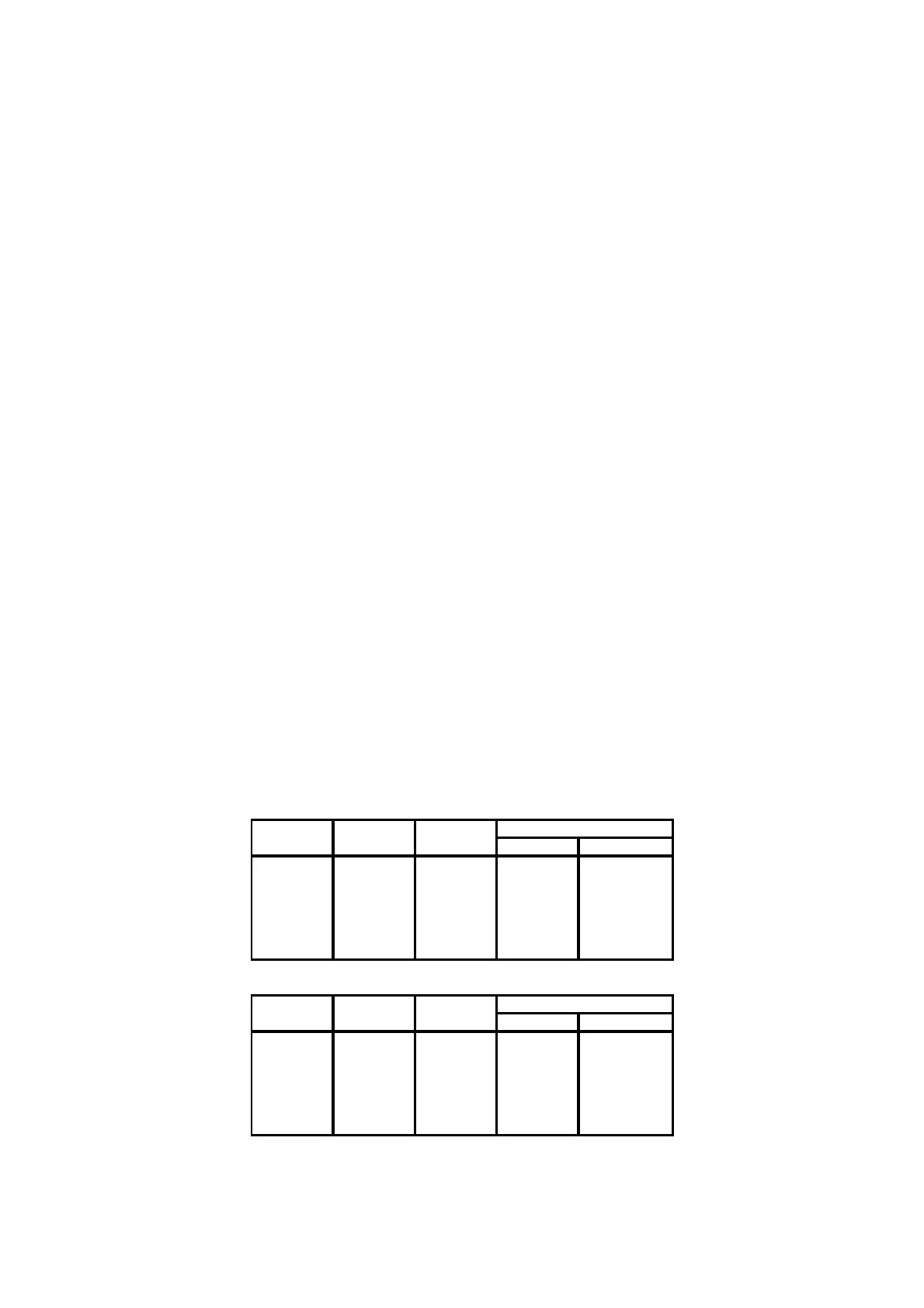
Table 13a: dV-DOSC DSP output channel assignment
and COMB connector summary (5+1 format presets)
DSP OUTPUT 5+1 FORMAT CO6 / CO24 COMB CONNECTOR
CHANNEL PRESET INPUT 3-WAY SUB
1 SUB (A) 1 SB118 or SB218
2 LO (A) 2 dV-SUB
3 MID (A) 3 dV-DOSC LO
4 HI (A) 4 dV-DOSC HI
5FULL (A)
6SUB (B)
AUX SUB DRIVE
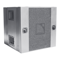
DSP OUTPUT 5+1 FORMAT CO6 / CO24 COMB CONNECTOR
CHANNEL PRESET INPUT 3-WAY SUB
1SUB (A)
2 LO (A) 2 dV-SUB
3 MID (A) 3 dV-DOSC LO
4 HI (A) 4 dV-DOSC HI
5FULL (A)
6 SUB (B) 1 SB118 or SB218