dV-DOSC dV-SUB Manual V3.0 June 2005 128
Connect the front and rear motors (or single motor) to dV-BUMP.
Slowly begin to raise the array. As the array lifts off, there will be a gap between the dV-SUB and dV-
DOSC. One person on either side can lift/rotate the block of 3 dV-DOSC into position and then
secure the front attachment points to dV-ANGLESD using 2 x dV-PIN25.
Steady the array as it lifts off the ground in order to prevent it from swinging and continue to lift the
array until it is freely floating in air. For single point hangs, use a digital inclinometer to verify that the
tilt angle of the top enclosure is correct before taking the array up to trim. If adjustment is required,
lower the array and change the pick point until the desired site angle is obtained.
Table 20: EXAMPLE PICK POINT REFERENCE CHART
(1 dV-SUB, 3 dV-DOSC, 7.5 deg between all dV-DOSC)
dV-BUMP Hole #
(0=front, 16=rear)
1-> 8 = center
9 -> 16 = ext bar
dV-BUMP Site Angle
(= top dV-DOSC site angle
provided 3.75 deg selected between
top dV-DOSC and dV-SUB)
1 +14.7 deg
2 +11.1 deg
3 +7.7 deg
4 +3.7 deg
5 +0.5 deg
6 -4.5 deg
7 -8.25 deg
8 -11.9 deg
9 -20.8 deg
10 -24.0 deg
11 -27.2 deg
12 -30.3 deg
13 -33.1 deg
14 -35.7 deg
15 -38.2 deg
16 -40.6 deg
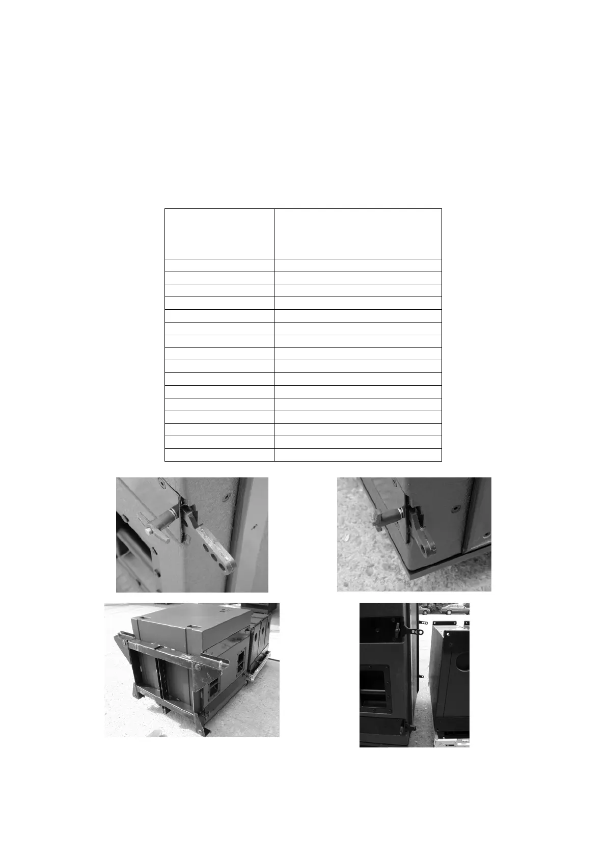
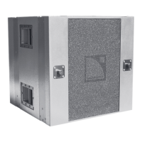
(i) dV-ANGLESDP pre-attached to the rear of dV-SUB
(ii) dV-ANGLESD pre-attached to the front of dV-SUB
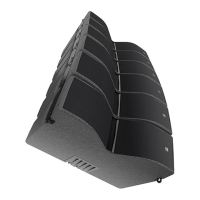
(iii) dV-BUMP attached to dV-SUB using
4 x dV-ANGLESD and 8 x dV-PIN25
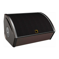
(iv) dV-DOSC located behind the array