Home
L-Acoustics
Stereo System
dV-SUB
L-Acoustics dV-SUB User Manual
4
of 1
of 1 rating
150 pages
Give review
Manual
Specs
To Next Page
To Next Page
To Previous Page
To Previous Page
Loading...
dV-DOSC dV-SUB Manual V3.0
June 2005
106
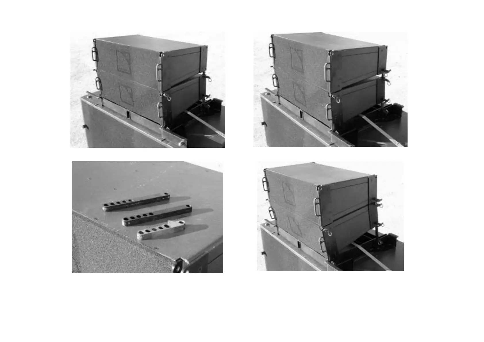
(ix) Second dV-DOSC placed into position
(x) then secured using dV-PIN25 (front first then rear)
(xi) Use dV-ANGLE N instead of dV-ANGLE P1…
(xii) for more downwards tilt
Figure 77: Stacking dV-DOSC on top of SB218 subwoofers
105
107
Table of Contents
Default Chapter
4
Table of Contents
4
Introduction
9
Wavefront Sculpture Technology™ Fundamentals
9
The Sound Reinforcement Problem
9
Wavefront Sculpture Technology Background
10
Figure 1: Wavefield Interference Compared to a Sculptured DV-DOSC Wavefield
10
Figure 2: Wavefront Sculpture Technology Criteria 1 and 2
11
First V-DOSC, Now DV-DOSC
12
Figure 3: Cylindrical Versus Spherical Wave Propagation
14
Summary of DV-DOSC Applications
15
Figure 4: Flown and Stacked DV-DOSC , DV-SUB Configurations
15
DV-DOSC TRAINING and QUALIFICATIONS
16
Qualified V-Dosc Technician (Qvt)
16
Certified V-Dosc Engineer (Cve)
16
1 THE DV-DOSC SYSTEM STANDARD
17
Figure 5: DV-DOSC 3-Way System Configuration
18
Figure 6A,B: DV-DOSC 4-Way System Configuration COMB and Cabling Options
19
DV-DOSC System Components
21
Loudspeaker Enclosures
21
Rigging Accessories
21
Figure 7: DV-DOSC Plus Accessories
21
Figure 8: DV-DOSC Rigging Accessories
22
Subwoofer Enclosures
23
Figure 9: DV-DOSC Subwoofer Options
23
Subwoofer Rigging Accessories
24
Amplification
24
Figure 10: Subwoofer Rigging Accessories
24
Figure 11: L-ACOUSTICS La24A, La48A Power Amplifiers
24
Amplifier Racks
25
Figure 12: Amplifier Rack Options and Accessories
26
Signal Distribution and Cabling
27
Figure 13: Signal Distribution and Cabling
28
Loudspeaker Cabling
29
Figure 14: Loudspeaker Cabling Options
30
DV-DOSC SPECIFICATIONS
31
Figure 15: DV-DOSC Enclosure - Front and Rear Views
31
Figure 16: DV-DOSC Array
31
DV-DOSC RIGGING SYSTEM
32
Figure 17: DV-ANGLE P1 and P2 Angle Values
32
Figure 18: DV-BUMP and DV-BUMP2 Rigging Bumpers
33
Figure 19: DV-DOWN
33
DV-SUB ENCLOSURE DESCRIPTION
34
Figure 20: DV-SUB
34
DV-SUB RIGGING SYSTEM
35
Figure 21: DV-ANGLESS Sub-To-Sub Angle Bar
35
Figure 22: DV-ANGLESDP and Dvanglesd Angle Bars
35
Figure 23: Illustration of DV-SUB Rigging Configurations
36
Table 1: Maximum Rated DV-SUB / DV-DOSC Combinations - with Extension Bar
36
Table 2: Maximum Rated DV-SUB / DV-DOSC Combinations - Without Extension Bar
36
POWERING DV-DOSC
37
Table 3: DV-DOSC Power Handling and Recommended Power Amplifier Ratings
37
Powering Subwoofers
38
Table 4: L-ACOUSTICS La24A MLS Settings for Use with DV-DOSC
38
Table 5: L-ACOUSTICS La48A MLS Settings for Use with DV-DOSC
38
Table 6: SB118 Power Handling and Amplification
38
Table 7: DV-SUB Power Handling and Amplification
38
Table 8: SB218 Power Handling and Amplification
38
DV-DOSC AMP PANELS
39
Figure 24: DV-DOSC Pado4A Amplifier Rack Panel
39
Figure 25: DV-DOSC Pado2A Amplifier Rack Panel
39
Figure 26: Pado4A Amp Rack Wiring
40
Table 10: Pado4A Internal Amp Rack Wiring Chart
40
Table 9: Pado4A COMB Wiring Chart
40
Figure 27: Pado2A Amp Rack Wiring
41
Table 11: Pado2A COMB Wiring Chart
41
Table 12: Pado2A Internal Amp Rack Wiring Chart
41
DV-DOSC AMPLIFIER RACKS
42
Figure 28: L-ACOUSTICS AMP RACK RK12-4
42
Figure 29: L-ACOUSTICS Amplifier Rack Options
43
Comb Connectors
44
Table 13A: DV-DOSC DSP Output Channel Assignment and COMB Connector Summary (5+1 Format Presets)
44
Figure 30: L-ACOUSTICS Rk122A Amplifier Rack Channel Assignments and Cabling
45
Figure 31: L- L-ACOUSTICS Rk124A Amplifier Rack Channel Assignments and Cabling
45
Table 13B: DV-DOSC DSP Output Channel Assignment and COMB Connector Summary (4+2 Format Presets)
45
Figure 32: L-ACOUSTICS Rk122A Amplifier Rack Channel Assignments and Cabling for 2-Way Stereo Presets
46
Figure 33: L-ACOUSTICS Rk122A Amplifier Rack Channel Assignments and Cabling for 3-Way Stereo Presets
46
Table 14: 2-Way and 3-Way Stereo Preset DSP Output Channel Assignment and COMB Connector Summary
46
Figure 34: L-ACOUSTICS Rk124A Amplifier Rack Channel Assignments and Cabling for 2-Way Stereo Presets
47
Figure 35: L-ACOUSTICS Rk124A Amplifier Rack Channel Assignments and Cabling for 3-Way Stereo Presets
47
Co24 Control Output Panel
48
Figure 36: CO24 Control Output Panel
48
Co6 Control Output Panel
49
Figure 37: MD24 Multi Distro Panel
49
Figure 38: CO6 Control Output Panel
49
Md24 Multi Distro Panel
49
Approved Digital Signal Processors
50
Oem Factory Presets
50
DV-DOSC PRESETS
51
Figure 39: DV-DOSC + DV-SUB 3-Way Stereo Preset Recommendations
51
Figure 40: Time Alignment Guidelines for 3-Way SB118 and SB218 Presets
53
Figure 41: Time Alignment Guidelines for 4-Way Presets
54
General Guidelines Regarding System Protection
55
Table 15: Recommended Limiter Threshold Settings
55
Table 16 : XTA DP224 Presets
56
Table 17: XTA DP226 Presets
57
Table 18: BSS FDS 366 Presets
58
Table 19: Lake Contour Preset Modules
59
2 DV-DOSC ARRAY SPECIFICATIONS
60
Coverage in the Horizontal Plane
60
Figure 42: Horizontal DV-DOSC Isocontour
60
Wavefront Sculpture in the Vertical Plane
61
Flat DV-DOSC Array
61
Convex Curvature DV-DOSC Array
61
Constant Curvature DV-DOSC Array
62
Variable Curvature DV-DOSC Array
62
Concave Curvature DV-DOSC Array
62
Coverage Predictions Using Array2004
63
Cutview Sheets
63
DV-ARRAY1, DV-ARRAY2 Input Data
63
Figure 43: Defining Cutview Dimensions
64
Figure 44: Parameters for the ROOM DIM Utility Sheet in ARRAY
64
Figure 45: ARRAY 2004 Geometric Data for DV-DOSC
65
Optimization Procedure
66
Figure 46 (A): Cutview Showing Non-Constant Enclosure Site Angle Impact Spacing for an 8 Enclosure Constant Curvature DV-DOSC Array (4.5 Degrees between All Enclosures)
66
Figure 46 (B): Cutview Showing Constant Enclosure Site Angle Impact Spacing for an 8 Enclosure Variable Curvature DV-DOSC Array (Inter-Enclosure Angles = 1, 1, 2, 3, 3.75, 5.5, 7.5 Degrees)
66
Figure 46 (C): Plan View Representation of Non-Constant (A) Versus Constant Spacing (B)
66
DV-DOSC Single Point Hang Utility
67
Figure 47: DV-DOSC Single Point Hang Simulation
67
DV-DOSC Downfill / Upfill Simulation
68
Figure 48: DV-DOSC Downfill Simulation (Tightly Wrapped)
68
Figure 49: DV-DOSC Downfill Simulation (Extended Coverage)
68
Figure 50: DV-DOSC Downfill Simulation (Circuiting Issues)
69
Figure 51: DV-DOSC Upfill Simulation
69
Output Data
70
H-Isocont Sheet
71
Input Data
71
Figure 52: DV-DOSC Mechanical Data
71
Optimization Procedure
72
Output Data
72
Figure 53: DV-DOSC Isocontour
72
Figure 54: ARRAY 2004 Spreadsheet Calculation Example
73
DV-DOSC COVERAGE MODELING USING SOUNDVISION
74
Figure 55: Plan View SPL Mappings at Octave Band Frequencies for 12 DV-DOSC
75
Figure 56: Impact Coverage and SPL Mappings for 12 DV-DOSC
76
3 Sound Design
77
Stacked or Flown
77
Stacking Guidelines
78
Figure 57: Distributed, Field Level Stacked DV-DOSC Systems for Stadium Sound Reinforcement
78
Rigging Guidelines
79
Figure 58 A,B,C: Flown System Examples
79
Achieving Optimum Coverage
80
The Left/Right Configuration
80
Tradeoffs between Intelligibility and Stereo Imaging
81
Figure 59: Tradeoffs between Intelligibility Versus Stereo Imaging
81
LEFT/CENTRE/RIGHT (LCR) Configurations
82
Figure 60: LCR Configuration for Theatrical Sound Reinforcement (L/R=V-DOSC, C=DV-DOSC)
82
Figure 61: LCR System Example
82
Multiple Array Concepts
83
Figure 62: Generic Rigging Plot (Main L/R FOH and LL/RR Offstage Fill Arrays)
83
Subwoofers
84
General Guidelines for the Use of Subwoofers
84
Flown DV-DOSC, Ground Stacked SB Subwoofers (3-Way System Operation)
85
Figure 63: Flown DV-DOSC and Ground Stacked SB218 3-Way System Configurations
85
Figure 64: Flown DV-DOSC and Ground Stacked Subwoofer Time Alignment
85
Physically Coupled DV-Sub/DV-DOSC (3-Way System Operation)
86
Figure 65: Physically Coupled Subwoofer Configurations
86
Figure 66: Hybrid Stacked/Flown DV-Dosc/DV-SUB Arrays and Centre Cluster
87
Hybrid Flown/Ground Stacked Subwoofers (4-Way System Operation)
88
Figure 67: Hybrid Flown/Stacked Subwoofer Configurations
88
Time Alignment: Flown/Ground Stacked Subwoofers
89
Preset Selection: Flown/Ground Stacked Subwoofers
89
Figure 68: Recommended Time Alignment Location for Flown DV-SUB, Ground Stacked L/R Subwoofers
89
Large Format Flown/Ground Stacked Subwoofer Configurations
90
Figure 69: Flown L/R DV-SUB Options for Larger System Configurations
90
Subwoofer Arraying Techniques
91
Left/Right Configurations
91
Figure 70: L/R Ground Stacked Subwoofer Arraying Techniques
92
Figure 71: Flown L/R Subwoofers Integrated with DV-DOSC Offstage Fill Arrays
92
Central Line Array with Electronic Delay Processing
93
Figure 72: Centre Subwoofer Line Array (A) Without and (B) with Electronic Delay Processing
93
Left/Centre/Right Configurations
94
Figure 73: Electronic Delay Processing Examples Using a 4- or 6-Channel DSP
94
Figure 74: LCR Subwoofer Arraying Techniques
95
4 Installation Procedures
96
Stacked Systems
96
Stacking DV-DOSC Standalone
96
Figure 75: Stacking DV-DOSC Using DV-BUMP Plus the V-DOSC Bumper
99
Stacking on Top of V-DOSC
100
Figure 76: Stacking DV-DOSC on Top of V-DOSC for Upfill/Longthrow
102
Stacking on Top of SB218 Subwoofers
103
Figure 77: Stacking DV-DOSC on Top of SB218 Subwoofers
106
Stacking DV-SUB Subwoofers
107
Figure 78: Stacking DV-SUB Subwoofers
108
Stacking DV-DOSC on Top of DV-SUBS
109
Procedure 1: Stacking Without DV-BUMP
109
Figure 79: DV-ANGLESD, DV-ANGLESDP Angle Bars
109
Figure 80: Stacking DV-DOSC on Top of DV-SUB Subwoofers (Without DV-BUMP or DV-BUMP2)
111
Procedure 2: Stacking with DV-BUMP or DV-BUMP2
112
Figure 81: Stacking DV-DOSC on Top of DV-SUB Subwoofers with DV-BUMP (or DV-BUMP2)
113
Flown Systems
114
Standalone Rigging with DV-BUMP or DV-BUMP2
114
Figure 82: Rigging DV-DOSC Standalone with DV-BUMP (or DV-BUMP2)
119
Trim and Angle Adjustments
120
Figure 83: Flown DV-DOSC Array Trim and Site Angle Adjustment
120
Rigging DV-DOSC under V-DOSC with DV-DOWN
121
Figure 84: Rigging DV-DOSC below V-DOSC for Downfill
124
Rigging DV-SUB Standalone
125
Figure 85: Rigging DV-SUB Standalone
126
Rigging DV-DOSC under DV-SUB (3+1 Configuration)
127
Table 20: EXAMPLE PICK POINT REFERENCE CHART
128
Figure 86: Rigging DV-DOSC under DV-SUB (Small Configuration)
129
Rigging DV-DOSC under DV-SUB (Larger Configurations)
130
Procedure 1 (2 DV-SUB + 6 DV-DOSC)
130
Procedure 2 (Larger Configurations)
131
Table 21: EXAMPLE PICK POINT REFERENCE CHART
131
Figure 87: Rigging DV-DOSC under DV-SUB (Larger Configuration - Procedure 1)
133
Figure 88: Rigging DV-DOSC under DV-SUB (Larger Configuration - Procedure 2)
135
Table 22: Maximum Rated DV-SUB / DV-DOSC Combinations - with Extension Bar
136
Table 23: Maximum Rated DV-SUB / DV-DOSC Combinations - Without Extension Bar
136
5 Maintenance and Installation Tools
137
Recommended Maintenance Procedures
137
Recommend Maintenance Tools
137
Spare Parts
137
Table 24: Recommended Maintenance Tools
137
Recommended Installation Tools
138
Figure 89: Recommended Installation Tools
138
6 Specifications
139
DV-DOSC SPECIFICATIONS
139
Figure 90: DV-DOSC Enclosure - Line Drawing
140
Table 25: DV-DOSC Weight Per Number of Cabinets
140
Figure 91: DV-BUMP - Line Drawing
141
DV-SUB SPECIFICATIONS
142
Figure 92: DV-SUB Line Drawing
143
APPENDIX 1: How Does DV-DOSC Behave with Respect to WST Criteria
144
Figure 93: Front View of DV-DOSC Array and Vertically Stacked DOSC Waveguides
144
APPENDIX 2: How Does the DOSC Waveguide Work
145
Figure 94: DOSC Waveguide - Internal Section
145
Rigging Certification
147
4
Based on 1 rating
Ask a question
Give review
Questions and Answers:
Need help?
Do you have a question about the L-Acoustics dV-SUB and is the answer not in the manual?
Ask a question
L-Acoustics dV-SUB Specifications
General
Brand
L-Acoustics
Model
dV-SUB
Category
Stereo System
Language
English
Related product manuals
L-Acoustics dV-DOSC
150 pages
L-Acoustics KIVA
48 pages
L-Acoustics 112XT
51 pages