LACO ORIGINAL OPERATING INSTRUCTIONS TITANTEST™
40
© 2018 LACO TECHNOLOGIES, INC. - [TitanTest itna01en1-07 BA.fm] - 1807
Once the part is filled, the gas filling station used must trigger the input pin
12 on the D-sub plug of the T
ITANTEST™. The electrical properties of the inter-
face are described more specifically, see Chapter 11.: "Interfaces and Proto-
cols", page 105.
► In order to test components already pre-filled with tracer gas, set the
External Trigger to "disabled".
Define the Rejection Type The selection of the rejection type depends on whether you would like to
test the test part in a vacuum chamber or according to the spraying method.
► Select "Q last" for tests in a vacuum chamber.
The device determines the test result on the basis of the leakage rate
measured at the end of the measuring time.
► Select "Q max" for tests according to the spraying method.
The device determines the test result on the basis of the maximum
leakage rate measuring during the measuring time.
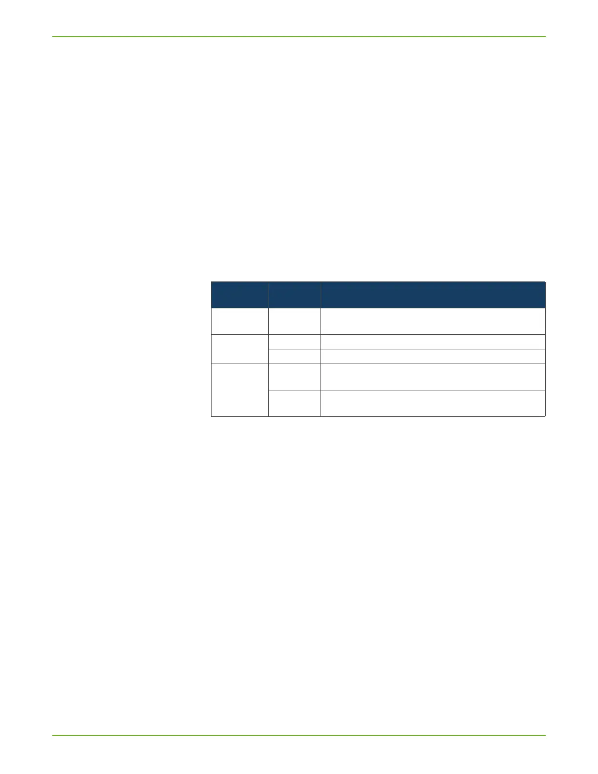
Overview Table
Process diagrams The following process diagrams show where in the Auto Test process the set
values become effective.
Table 18: Auto Test Settings
Option Value range
(Min. Max.)
Comment
Background Limit Value from - to Maximum allowed tracer gas background before beginning the measure-
ment.
External Trigger Disabled No function
Enabled Active
Rejection type Q last The device determines the test result on the basis of the leakage rate mea-
sured at the end of the measuring time.
Q max The device determines the test result on the basis of the maximum leakage
rate measuring during the measuring time.