OPERATION
The function
of
the governor is to maintain, within certain limits, a desired engine speed, even
though the operating load may vary.
The governor assembly rotates with the crankshaft. As engine RPM increases the four steel
balls move up ramps forcing the governor assembly to slide down on the crankshaft. This
downward force is counterbalanced by the governor spring which holds the throttle open.
Governor spring tension tends to open the throttle. The action
of
the steel balls, which are
controlled by centrifugal force tends to close the throttle. The engine RPM at which these
two
forces balance is called the governed speed. The governor RPM is changed by adjusting
governor spring tension.
ADJUSTMENT
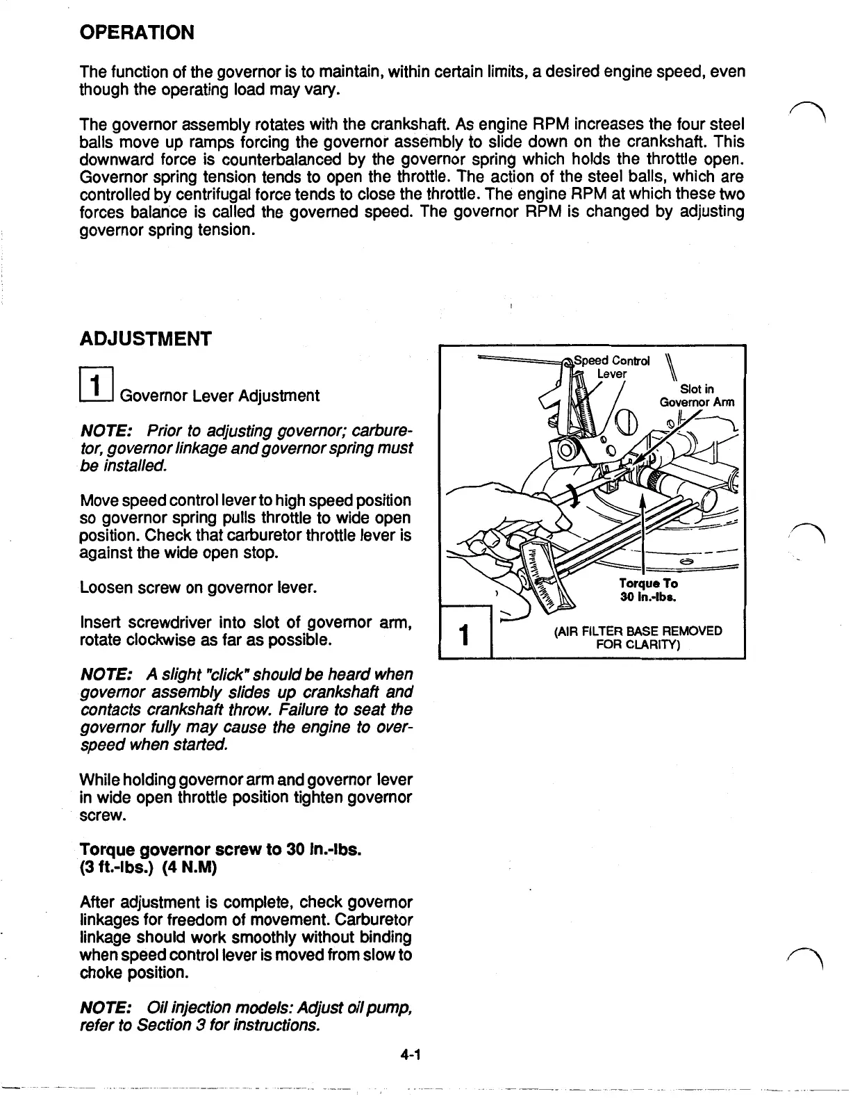
Governor Lever Adjustment
NOTE: Prior to adjusting governor; carbure-
tor, governor linkage and governor spring must
be installed.
Move speed control lever to high speed position
so
governor spring pulls throttle to wide open
position. Check that carburetor throttle lever
is
against the wide open stop.
Loosen screw on governor lever.
Insert screwdriver into slot of governor arm,
rotate clockwise
as
far as possible.
NOTE: A slight "click" should be heard when
governor assembly slides
up
crankshaft and
contacts crankshaft throw. Failure to seat the
governor fully may cause the engine to over-
speed when started.
While holding governor arm and governor lever
in wide open throttle position tighten governor
screw.
Torque governor screw
to
30
in.-lbs.
After adjustment
is
complete, check governor
linkages for freedom of movement. Carburetor
linkage should work smoothly without binding
when speed control lever is moved from slow to
choke position.
NOTE:
Oil injection models: Adjust oil pump,
refer
to
Section
3
for instructions.
(3
ft.-lbs.)
(4
N.M)
4-1
Lever
Slot
in
Governor
Arm
(AIR
FILTER
BASE
REMOVED
FOR
CLARITY)
I
 Loading...