6-24 LeeBoy Model 8616 Conveyor Paver
Operation
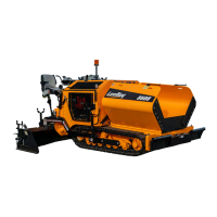
Element Connections
The bottom of the control box contains the system
element breakers, and the 6 main outputs for the screed
heating elements (Figure 6-29). Since the heating
elements are powered by 220VAC to 240VAC, each
element has two breakers (Figure 6-29,2). There is one
breaker for each leg of each element. Also shown is one
of the two pin plugs that supplies power to the screed
elements.
Any element lead can be plugged into any supply plug
Figure 6-29,1) under the heating control/distribution
box. All six plugs are equally rated.
Electric Heat Control Box Bottom and Breakers
Figure 6-29
1 - Element Lead
2 - Breaker
NOTE: All control boxes are manufactured the same
totallscreedandpavercombinations.Ifyour
screed does not have enough element wires
tollalltheplugsonthebottomofthecontrol
box, it may be normal. Any plugs that are not
lledshouldbecappedwithappropriateplug
terminator.
Electrocution Hazard! If there is no
heat on any screed when screed heat system is
turned on, a screed wiring fault should be assumed.
A wiring fault could cause an electrical shock that
could result in serious injury or death. Do not operate
the LeeBoy Model 8616 Conveyor Paver until wiring
fault is corrected. (
See “Maintenance” on page 7-1.)
2
4
3
Generator Rear View
Figure 6-28
1 - Power Cable
2 - L1 (Black Wire)
3 - L2 (White Wire)
4 - Generator Winding Wire
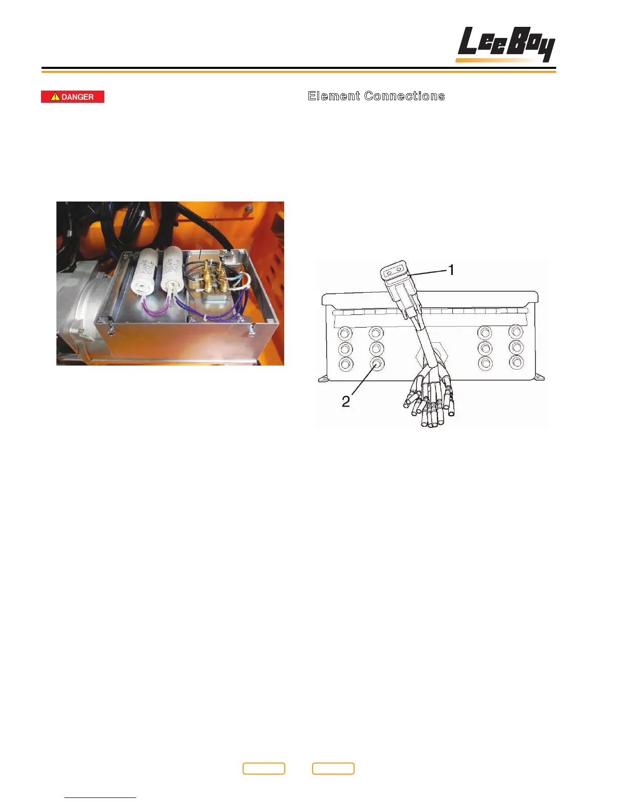
The rear of the generator is shown here (Figure 6-28).
You can see the power cable (Figure 6-28, 1) coming
into the generator case at the top right. Just below the
generator case is the voltage capacitor. The capacitor
controls the output voltage of the generator, and may
need to be changed if no voltage is generated by the set
(see Generator Voltage Testing in Section 7).
The main output of the generator is located in the lower
left of the picture. You will see two main wires attached
to the generator, a black wire (Figure 6-28,2), and a
white wire (Figure 6-28,3). The other two wires (Figure
6-28,4) are generator winding wires, and should not
need to be serviced under normal circumstances.
Return to
Last Viewed
Return to
Thumb Index