6
LeeBoy Model 8616 Conveyor Paver 6-25
Operation
Each element output from the bottom of the box consists
of two wires
.
One wire will connect to the L1 circuit, and
the other wire will connect to the L2 circuit
.
The L1 circuit
is the left bank of element breakers
.
Each breaker has
two terminals
.
One terminal is connected to the main
input, and the other terminal is connected directly to an
element output wire
.
The L2 circuit is the right bank of
element breakers.
This bank is wired slightly different,
in that each leg not only goes from the main L2 power
lead through a breaker, but each leg then goes through
one of the six contacts on the element relays.
It is these
relays that “make” or “break” the circuit to each element
to start or stop the heating cycles
.
An element relay is shown here (Figure 6-31)
.
There
are three relays in the control box
.
Each relay has two
separate sets of contacts operated by one coil
.
Element Relay
Figure 6-31
1 - Coil Terminals
2 - Contact Terminals
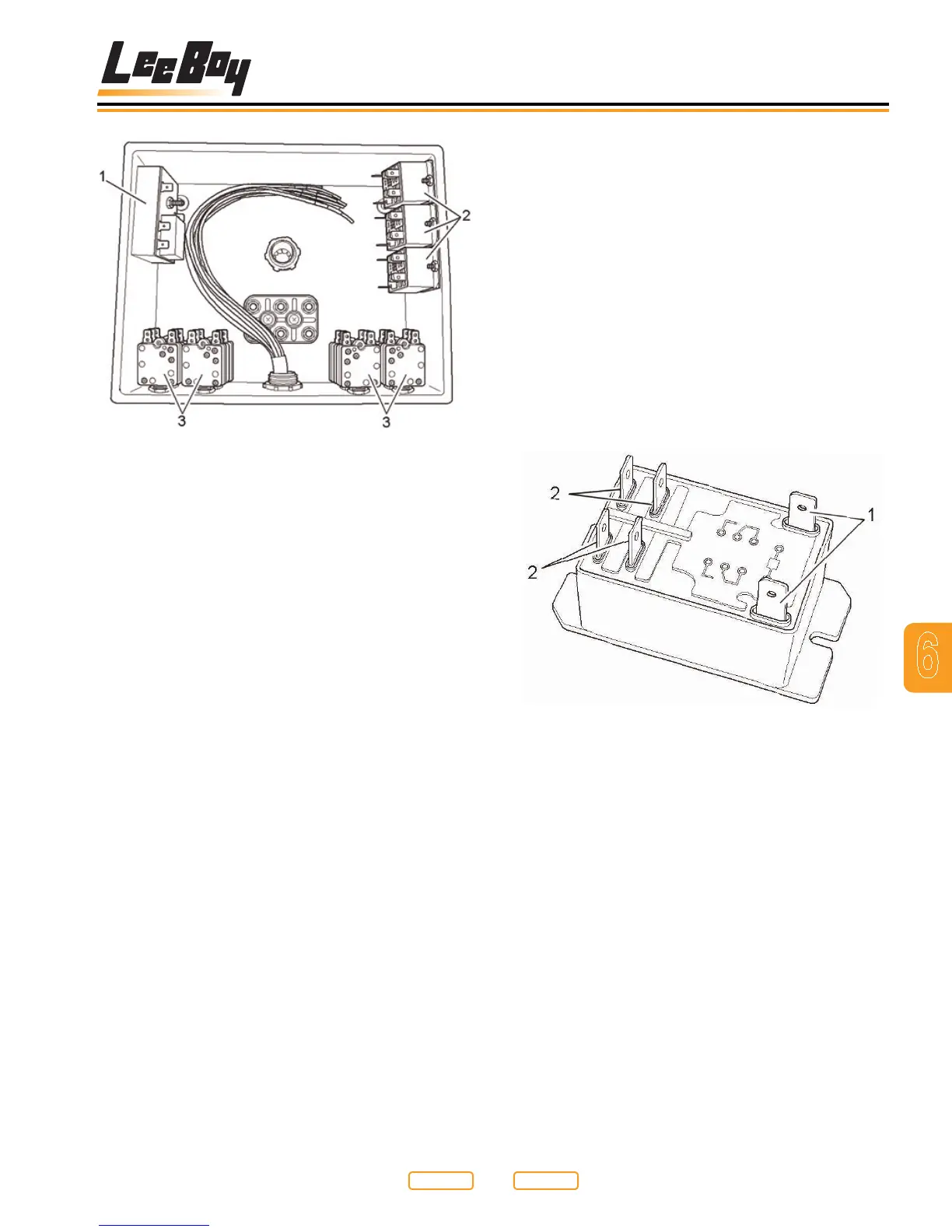
Electric Heat Control Box Before Wiring Completed
Figure 6-30
1 - System Timer
2 - Element Relays
3 - Element Breakers
The control box consists of three major types of
components. The system timer (Figure 6-30,1) is
located in the upper left hand corner of the box. The
element relays (Figure 6-30,2) are located in the upper
right hand corner of the box, and the element breakers
(Figure 6-30,3) are located in the lower surface of
the box. The other block in the center is used as a wire
junction block only. Refer to the wiring schematic at the
end of this manual, and you will note how the following
connections are made.
Return to
Last Viewed
Return to
Thumb Index