6-26 LeeBoy Model 8616 Conveyor Paver
Operation
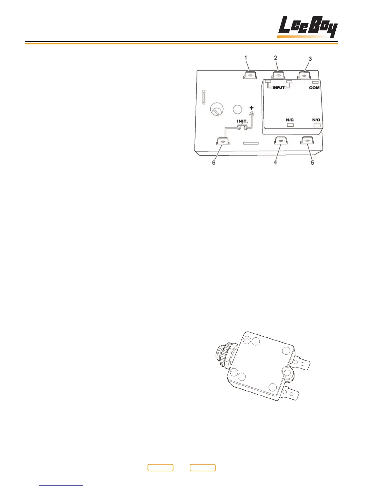
Heat System Timer Terminals
Figure 6-32
1 - Ground Input
2 - Power Input
3 - Common (COM)
4 - Terminal Output
5 - Terminal Output
6 - Initiate Terminal
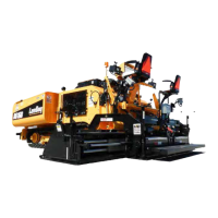
The breakers are wired into each leg of each element.
If an element has a fault, either in the wiring, or in the
element itself, the breaker will trip and power will
no longer be applied to that leg of the element. The
breakers can be manually reset by depressing the trip
button back in when they are extended. If by depressing
the breaker re-set, the breaker will not reset, there
may be a need to replace the breaker, or diagnose the
element, or element wiring, it is connected to.
Element Breaker
Figure 6-33
The coil contacts on the relay shown are at the top and
bottom of the right hand side of the relay (Figure 6-31,
1)
. One set of contacts are the two terminals at the top
left of the relay, and the other set of contacts (Figure
6-31,2) are at the bottom left of the relay shown. When
the coil is energized, both sets of contacts will close.
All the relays used are “normally open” (see Testing
Element Relays in Section 7).
A heat system timer is shown (Figure 6-32). There are
six terminals on the timer. The top two left terminals are
the main 12VDC input terminals for the timer. The ground
(Figure 6-32,1) is on the left and the power (Figure
6-32,2) is on the right.
The top right terminal is the common terminal (Figure
6-32,3) to the internal timer relay that controls the heat
system. When power is applied to the input terminal, it
is also jumped to the common (or COM) terminal on the
timer. The lower right two terminals on the timer are the
outputs of the internal timer relay.
The left of these two is the normally closed terminal
(Figure 6-32,4), which is not used in this system, and
the lower right terminal (Figure 6-32,5) is the normally
open terminal. The normally open terminal is used as
the output terminal to “turn” the heating system on. The
lower left hand terminal (Figure 6-32,6) is the “initiate”
contact. When the HEAT ON button is depressed,
12VDC is momentarily applied to this terminal to start
the timer cycle. During the timer cycle, power will not be
applied to this terminal unless the HEAT ON button is
depressed again. Keep in mind, if this happens, the timer
will re-start.
Return to
Last Viewed
Return to
Thumb Index