3. SAF ET Y NOTES
3.3 Laser safety
3.3.1 Safety switch (interlock) on the microscope
Two safety switches are integrated into the microscope us-
ing a laser safety kit option. These must be integrated into
the laser safety concept so that the light path of the laser
beam is interrupted when the interlock switch is opened.
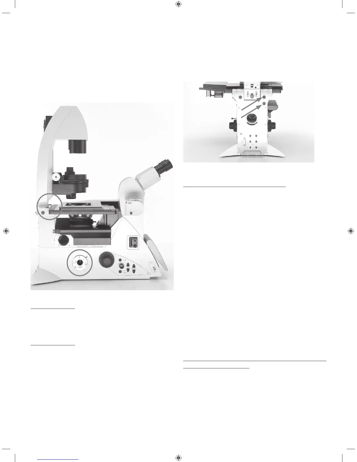
1
2
Interlock switch (1) and (2)
Interlock switch 1:
An interlock switch is integrated on the Transmitted Light
arm and activated when the Transmitted Light arm is folded
back (interlock switch opens).
Interlock switch 2:
An additional interlock switch is also installed in the micro-
scope, which is activated (interlock switch opens) when
the beam path to the eyepiece is released.
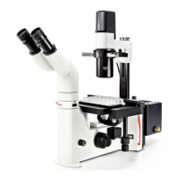
Two equivalent interlock connectors, which lead to the
microscope's interlock switch, are attached to the back of
the microscope. The interlock connector of the microscope
must be connected to your laser beam interrupter.
Interlock connectors on the rear side of the stand
Technical data for the interlock connector:
Plug:
Manufacturer: Binder
Type: 09-0097-20-05
(5-pin flange plug,
711 series subminiature round plug connector)
Compatible coupling:
Manufacturer: binder
Type: 99-0096-102-05
(5-pin cable socket,
711 series subminiature round plug connector)
Type: 79-1414-12-05
(5-pin cable socket with 2m cable,
702 series subminiature round plug connector)
Type: 99-0414-00-05
(5-pin cable socket,
712 series subminiature round plug connector)
Pin assignment:
Switching contact between pin 1 and pin 5.
Maximum permitted electrical characteristic values of the
integrated interlock switch:
Umax= 40 V DC
Imax= 0.2 A
11