5. OPERATION - TRANSMIT TED LIGHT CONTR AST ME THOD
5.13.7 Integrated Modulation Contrast – IMC (TL)
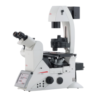
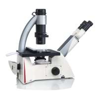
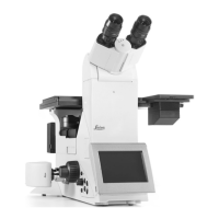
Leica DMi8 with manual Transmitted Light method
t*GOFDFTTBSZTFUUIF5-#SJHIUmFMEQPTJUJPOPSBOFNQUZ
position on the fluo turret, or select the "DAPI-TL" filter
cube.
t4FMFDUB#SJHIUmFMEPCKFDUJWFXJUIeyepoint B or C.
t4XJOHBMMSFNBJOJOHPQUJDBMDPNQPOFOUTTVDIBTUIFBOB-
lyzer or IC prisms from the beam path.
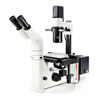
Inserting the IMC module:
t*GOFDFTTBSZSFNPWFUIFDPWFSPGUIFIPMEFSBOEJOTFSU
the IMC module evenly from the front on the left side of
the microscope.
For a tiltable Transmitted Light arm:
t4MJEFUIF*.$NPEVMFJOUPUIFDPSSFDUFZFQPJOU#PS$
For a fixed Transmitted Light arm:
t*OTFSUUIF*.$NPEVMBUPSJOUPUIF*.$NPEVMFGSPNUIF
side according to the eyepoint B, C or D of the objec-
tive.
Ensure that the "TOP" marking faces upwards.
t&OHBHFUIFTMJEFJOUIF*.$QPTJUJPO
(Push in for IMC, pull out for the Brightfield).
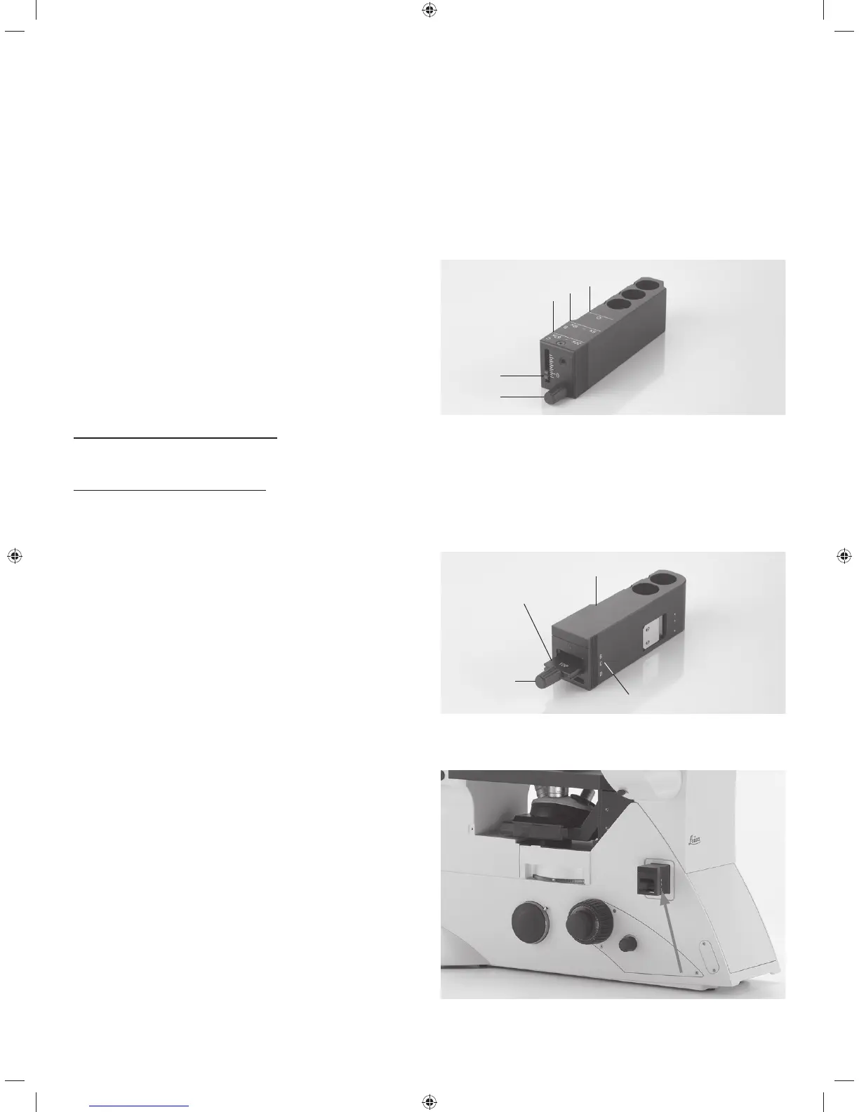
IMC module for fixed Transmitted Light arm
1 IMC module
2 IMC modulator
3 Fine adjustment
4 Positioning depending on eyepoint B, C or D
IMC module for tiltable Transmitted Light arm
1 Position for objectives with eyepoint C
2 Position for objectives with eyepoint B
3 Brightfield position
4 Height adjustment
5 Fine adjustment
1
2
3
4
5
1
2
3
4
IMC module used for fixed Transmitted Light arm
78