t5PVDI4DSFFOPOMZGPSNPUPSJ[FE-FJDB%.J
t#VUUPOGPS5-'MVPSUPHHMJOH
tCVUUPOTGPSNPUPSJ[FEBQFSUVSFEJBQISBHNBEKVTUNFOU
tCVUUPOTGPSNPUPSJ[FEJMMVNJOBUFEmFMEEJBQISBHNBEKVTUNFOU
tCVUUPOGPSPQFSBUJOHUIFNPUPSJ[FETIVUUFS
tWBSJBCMFGVODUJPOLFZT
tPQFSBUJOHCVUUPOTGPSGPDVTUISFTIPMETPOMZGPSFMFDUSPOJDGPDVTJOH
tIBOEXIFFMTGPSGPDVTJOH
t3PUBSZLOPCGPSTFUUJOHUIFCSJHIUOFTT
tCVUUPOTGPSnVPSFTDFODFDVCFT
tCVUUPOTGPSPCKFDUJWFT
t-FJDB4NBSU.PWFFSHPOPNJDDPOUSPMFMFNFOUGPSNPOJUPSJOHYZ[BOEBEEJUJPOBMWBSJ
t-FJDB451PQFSBUJPOWJBFYUFSOBM5PVDI4DSFFO
t-FJDB451PQFSBUJPOWJB5PVDI4DSFFOVTJOHDPOUSPMFMFNFOUGPSNPOJUPSJOHYZ[BOE
t4XJUDISPETGPSPQFSBUJOHUIFQPSUNBOVBMTIVUUFSBOE.BHOJmDBUJPO$IBOHFS
t4MJEFSGPSNBOVBM'*.*.$BOE*1$BEKVTUNFOU
t4XJUDISPEGPSPQFSBUJOHUIFJOmOJUZQPSU
t
t-FJDB$53
t-FJDB$53"EWBODFE
t-FJDB$53"EWBODFEXJUIPVUQPXFSTVQQMZ
t-FJDB$53"EWBODFE
t4FSWJDFQPSUGPSTBWJOHMPBEJOHNJDSPTDPQFTFUUJOHTWJBUIF5PVDI4DSFFO
tY*¤$GPSFYUFSOBMJOUFSOBMQFSJQIFSBMEFWJDFT
t$53CPYFT
tYJOUFSMPDLGPSMBTFSBQQMJDBUJPOT
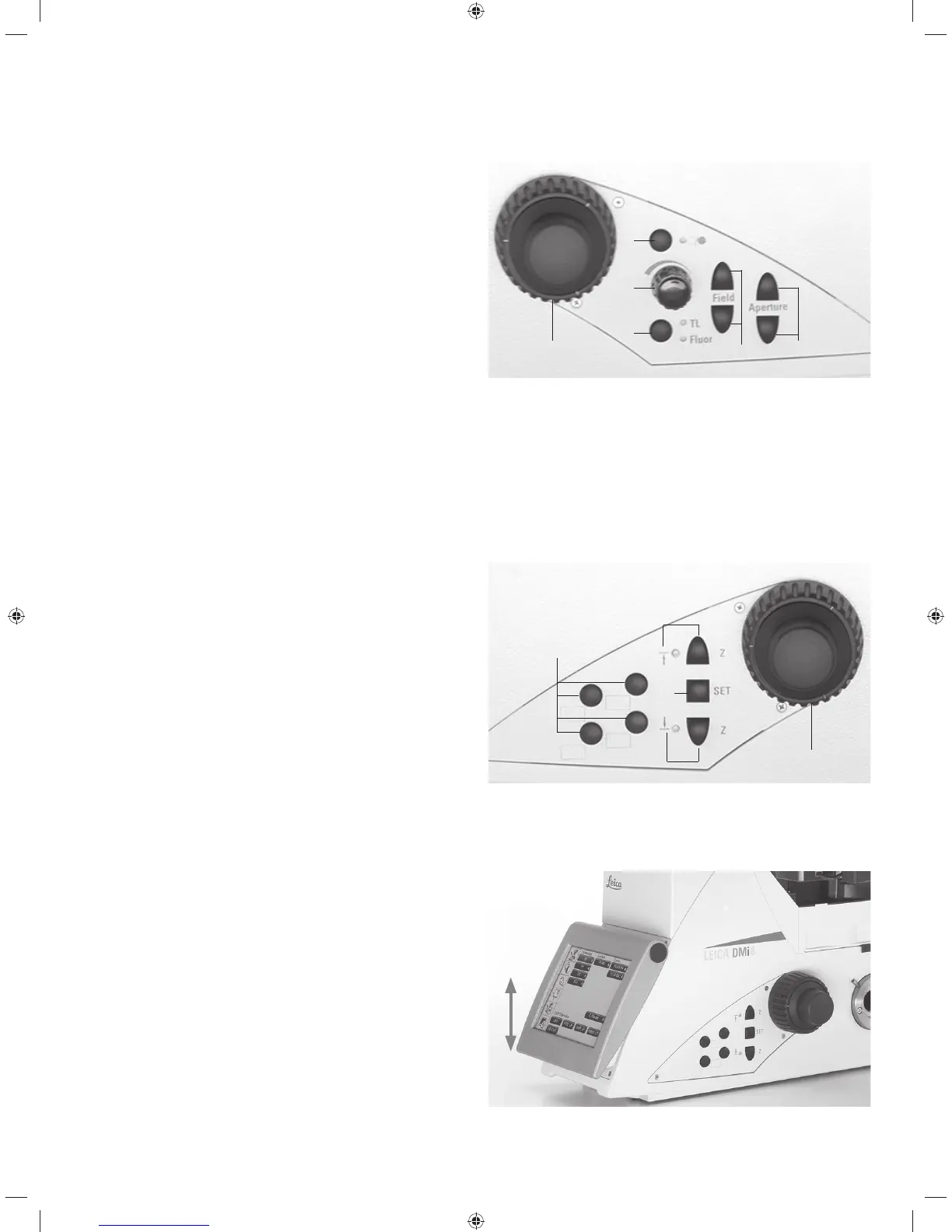
4.4.1 Control panel fields
Control panel field on the left microscope side
1 Motorized aperture diaphragm adjustment
2 Motorized illuminated field diaphragm adjustment
3 Motorized toggling between the TL/Fluor illumination axes
4 Adjusting the Transmitted Light brightness of the inten-
sity levels for the automated FIM (fluorescence inten-
sity manager)
An LED indicates the illumination method which is cur-
rently affected by the brightness adjustment.
5 Opening/closing the motorized shutter
or during manual shutter light control
An LED displays the state of the shutter:
LED on = shutter opened
LED off = shutter closed.
6 Focusing
1
2
3
4
5
6
Maximum system design of the left control panel field
The number of buttons may vary depending on the configu-
ration.
Control panel field on the right microscope side
1 Variable function keys (freely configurable)
The function keys are preassigned at the factory (see
"Identification Sheet" and S. 92
2 Focus threshold (the LED illuminates when the focus
threshold is set)
3 Setting the focus position and focus threshold
4 Focus position (the LED illuminates when the focus po-
sition is set)
5 Focusing
1
2
3
4
5
Maximum system design of the right control panel field
The number of buttons may vary depending on the configu-
ration.
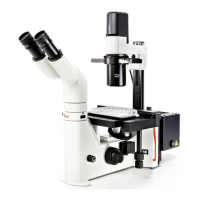
Control panel fields on the front side
Swiveling Touch Screen for adjusting all automated compo-
nents on the Leica DMi8.
Adjustable angle for better readability.
Refer also to the chapter titled "The Touch Screen" S. 34
29