PI1 Process Interface (optional)
60 Power Analyzer NORMA 4000, NORMA 5000
EO1111G REV G
Move the cursor to the field in line Drv1 and press Enter.
A list of possible options is displayed.
Select a value and confirm with Enter.
The value is now shown in the display field.
Save the configuration for the motor by pressing SAVE.
Press function key Next....
The settings for motor 2 are displayed.
Adjust settings for motors 2 to 4, following the above
instructions for motor 1.
Save the configurations for the motors by pressing SAVE.
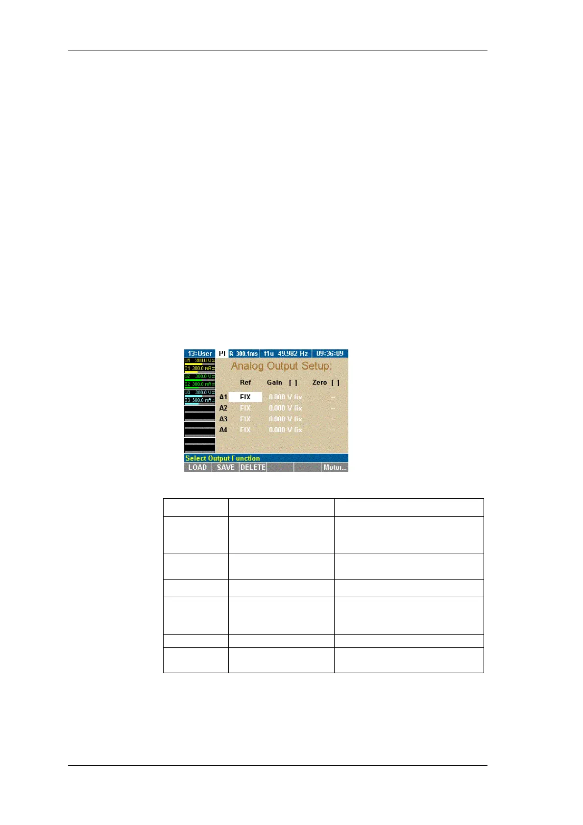
The 4 analog outputs (A1...A4) can be used to output the measured,
calculated or averaged values or to transfer them to an external
device for further processing. By default, the analog outputs are
configured as voltage output for ±10 V. In order to output higher
voltages, you must enter the relevant transducer ratio, e.g. 10 mV/V
for a measured voltage of 220 V and an output of 2.2 V.
Press function key A-Out.
The Analog Output Setup menu is displayed.
Adjust the settings as follows:
Column Settings Description
Ref FIX
U1, M1, P
M1
...
Fixed DC voltage, or
selection from available
average measured values
Gain 1...
Transducer ratio or fixed
value (-10.3 V to +10.3 V)
Column Settings Description
Unit
V/A, V/V, V/Ohm,
V/Hz (depending no
selected Ref)
e.g. 10 mV/V, i.e. 10 mV at
the output correspond to 1 V
of the measured value
Zero 1...
Set zero/offset
Unit
A, W, V, Hz, Ohm
Unit for zero, depending on
selected Ref
Move the cursor to a field in line A1 and press Enter.
A list of possible options is displayed.
Select a value and confirm with Enter.
The value is now shown in the display field.
Configure analog outputs A2 to A4 accordingly.
Configure other
motors
Configure analog
output