Appendix A. Hardware disassembling for recycle
Follow the instructions in this section to recycle components with compliance with local laws or regulations.
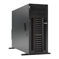
Disassemble the server for chassis recycle
Follow the instructions in this section to disassemble the server before recycling the chassis.
About this task
Attention:
• Read “Installation guidelines” on page 57 to ensure that you work safely.
• Power off the server and disconnect all power cords for this task.
• Prevent exposure to static electricity, which might lead to system halt and loss of data, by keeping static-
sensitive components in their static-protective packages until installation, and handling these devices with
an electrostatic-discharge wrist strap or other grounding system.
• If the server is in a rack, remove it from the rack.
• If foot stands are installed on the server, rotate them inwards and lay the server on its side for easier
operation.
Step 1. Remove the hot-swap redundant power supply. See “Remove a hot-swap power supply” on page
170.
Step 2. Remove all the installed drives and fillers. See “Remove a hot-swap drive” on page 83 or “Remove
a simple-swap drive” on page 80.
Step 3. Remove the server cover. See “Remove the server cover” on page 188.
Step 4. Remove the front door. See “Remove the front door” on page 107.
Step 5. Remove the front bezel. See “Remove the front bezel” on page 105.
Step 6. Remove the front panel board assembly. See “Remove the front panel board assembly ” on page
110.
Step 7. Remove the optical drives. See “Remove the 5.25-inch drive bay adapter assembly” on page 153
or “Remove an optical drive or a tape drive” on page 147.
Step 8. Remove the expansion drive cage. “Remove the expansion drive cage” on page 90.
Step 9. Remove the optical drive cage. See “Remove the optical drive cage” on page 144.
Step 10. Remove the T4 fillers. See “Remove a T4 filler” on page 203.
Step 11. Remove all the flash power modules. See “Remove a flash power module” on page 98.
Step 12. Remove the GPU filler. See “Remove a GPU filler” on page 116.
Step 13. Remove the air baffle. See “Remove the air baffle” on page 72.
Step 14. Remove the NVLink bridges. See “Remove an NVLink bridge” on page 141.
Step 15. Remove all the full-length GPU adapters. See “Remove a full-length GPU adapter” on page 113.
Step 16. Remove all the PCIe adapters. See “Remove a PCIe adapter” on page 162.
Step 17. Remove the PCIe adapter holders. See “Remove a PCIe adapter holder” on page 160.
Step 18. Remove all the fans. See “Remove a hot-swap fan” on page 93.
Step 19. Remove the fan cage. See “Remove the fan cage assembly” on page 95.
© Copyright Lenovo 2021 229

 Loading...


