Flashing slowly (once per second): The drive is being rebuilt.
Flashing rapidly (three times per second): The drive is being identified.
4 5 6 7 3.5-inch hot-swap drive bays
The drive bays are used to install 3.5-inch hot-swap drives. When you install drives, follow the order of the
drive bay numbers. The EMI integrity and cooling of the server are protected by having all drive bays
occupied. The vacant drive bays must be occupied by drive bay fillers or drive fillers.
Note: For 3.5-inch drive bay models that support NVMe drives, you can install up to eight NVMe drives in
bays 0-3 and 4-7.
8 Foot stands
For tower form factor models, the foot stands help the server stand steadily.
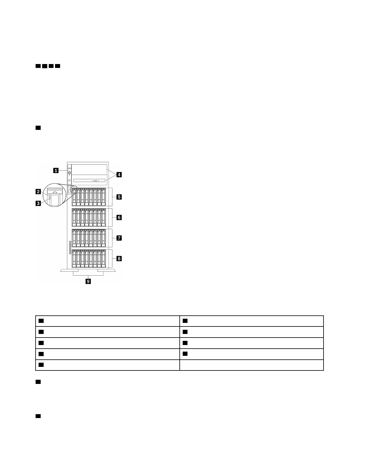
Server models with thirty-two 2.5-inch drive bays
Figure 7. Front view of server models with thirty-two 2.5-inch drive bays
Table 6. Components on server models with thirty-two 2.5-inch drive bays
1 Front panel 6 2.5-inch hot-swap dive bays 16-23
2 Drive activity LED (green)
7 2.5-inch hot-swap drive bays 8-15
3 Drive status LED (yellow)
8 2.5-inch hot-swap drive bays 0-7
4 Optical-drive bays 1-2
9 Foot stands
5 2.5-inch hot-swap drive bays 24-31
1 Front panel
For information about the controls, connectors, and status LEDs on the front panel, see “Front panel” on
page 21.
2 Drive activity LED (green)
20
ThinkSystem ST650 V2 Maintenance Manual

 Loading...


