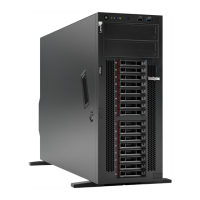
Figure 11. System board components
Table 10. Components on the system board
1 CMOS battery connector 21 SATA 0-3 connector
2 PCIe 2 connector 22 SATA 8-11 connector
3 PCIe 1 connector 23 Internal USB connector 3
4 Operator-information-panel connector 24 Internal USB connector 4
5 Power distribution board signal connector
25 TPM
1
/TCM
2
connector (for Chinese Mainland only)
6 Power distribution board power connector
26 PCIe slot 8 enable connector
3
7 Fan 4 connector
27 PCIe slot 9 (processor 1)
8 DIMM 17-24 slots (processor 2) 28 PCIe slot 8 (processor 2)
3
9 PCIe 3 connector 29 PCIe slot 7 (processor 2)
10 Fan 3 connector
30 PCIe slot 6 (processor 2)
11 Processor 2 socket
31 PCIe slot 5 (processor 2)
12 CFF RAID power connector 32 DIMM 9-16 slots (processor 1)
13 Fan 2 connector 33 Processor 1 socket
14 DIMM 25-32 slots (processor 2) 34 DIMM 1-8 slots (processor 1)
15 PCIe 4 connector
3
35 Intrusion switch connector
16 M.2 signal connector
36 PCIe slot 4 (processor 2)
17 Fan 1 connector
37 PCIe slot 3 (processor 1)
18 Front USB connector 38 PCIe slot 2 (processor 1)
34 ThinkSystem ST650 V2 Maintenance Manual

 Loading...


