Electrical installation − HighLine/StateLine version
Communication
CANopen®
6
101
EDS84DPS424 EN 5.0
6.7.3 CANopen®
X3x − communication
Pin Signal Description Data
Type: M12, 5−pole, A−coded
X31 −> pins
X32 −> sockets
84DPSO05_5
1 n. c. Not assigned
CAN specification
2 n. c. Not assigned
3 CG CAN−Ground
4 CH CAN−HIGH
5 CL CAN−LOW
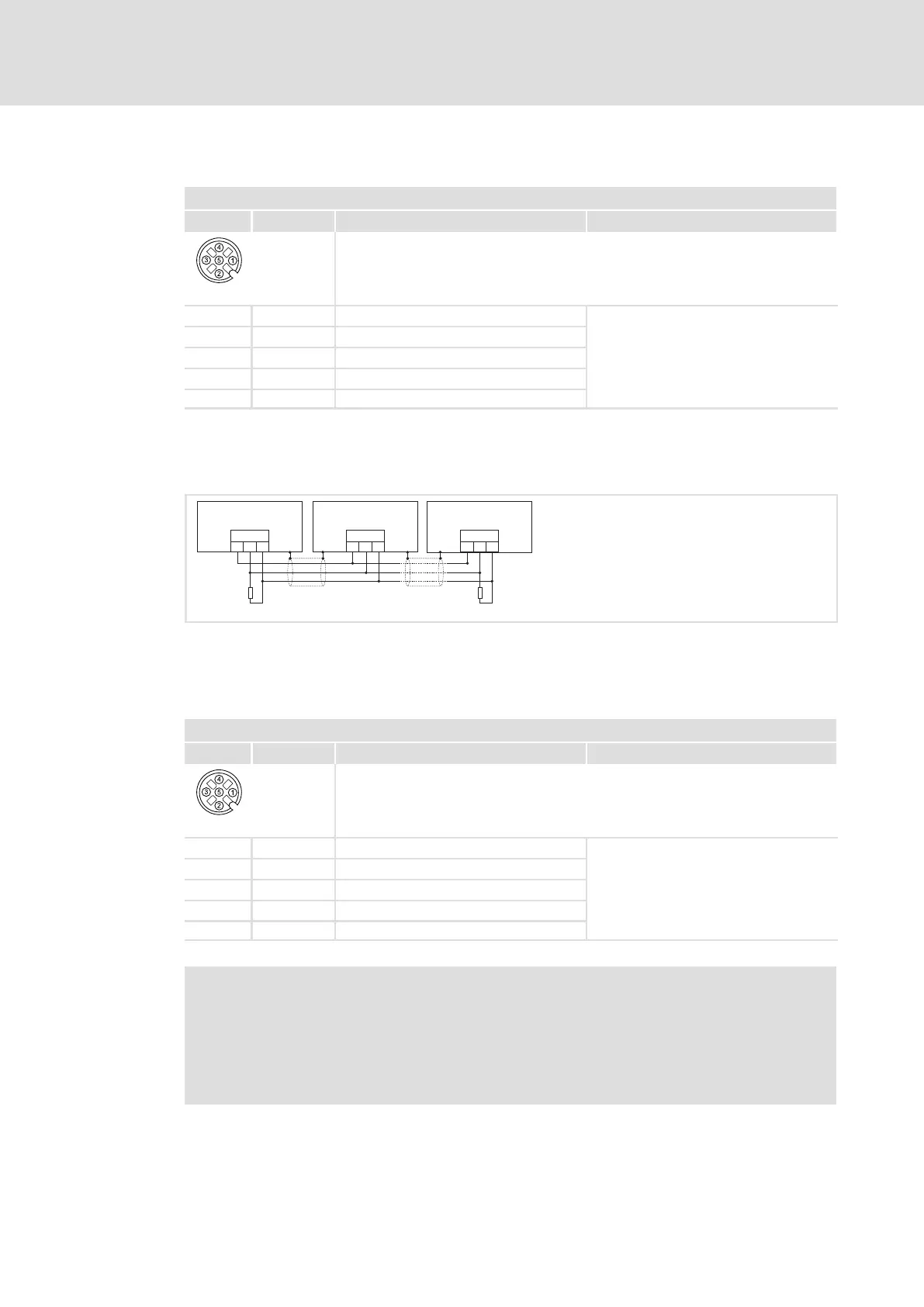
Example circuit
Wiring example
CG
CAN
LO HI CG
CAN
LO HI CG
CAN
LO HI
RR
A
n
A
2
A
1
EL100−009
Terminating resistors of 120 are not integrated and must be wired externally.
6.7.4 CAN on board
X35 − communication
Pin Signal Description Data
Type: M12, 5−pole, A−coded, sockets
84DPSO05_5
1 n. c. Not assigned
CAN specification
From HW version VD onwards, the 120
terminating resistor is integrated.
HW version: see C00210/10
2 n. c. Not assigned
3 CG CAN−Ground
4 CH CAN−HIGH
5 CL CAN−LOW
Software manual for the standard device / »Engineer« online help
Here, detailed information is provided about ...
ƒ CAN communication;
ƒ Parameter setting and configuration;
ƒ System bus (CAN) diagnostics.