Commissioning
Quick commissioning
Terminal control
8
146
EDS84DPS424 EN 5.0
8.3.2 Terminal control
Commissioning steps
1. Wiring of power terminals
Make use of the Mounting Instructions supplied with the frequency inverter to wire the
power terminals according to the requirements of your device.
2. Wiring of control terminals.
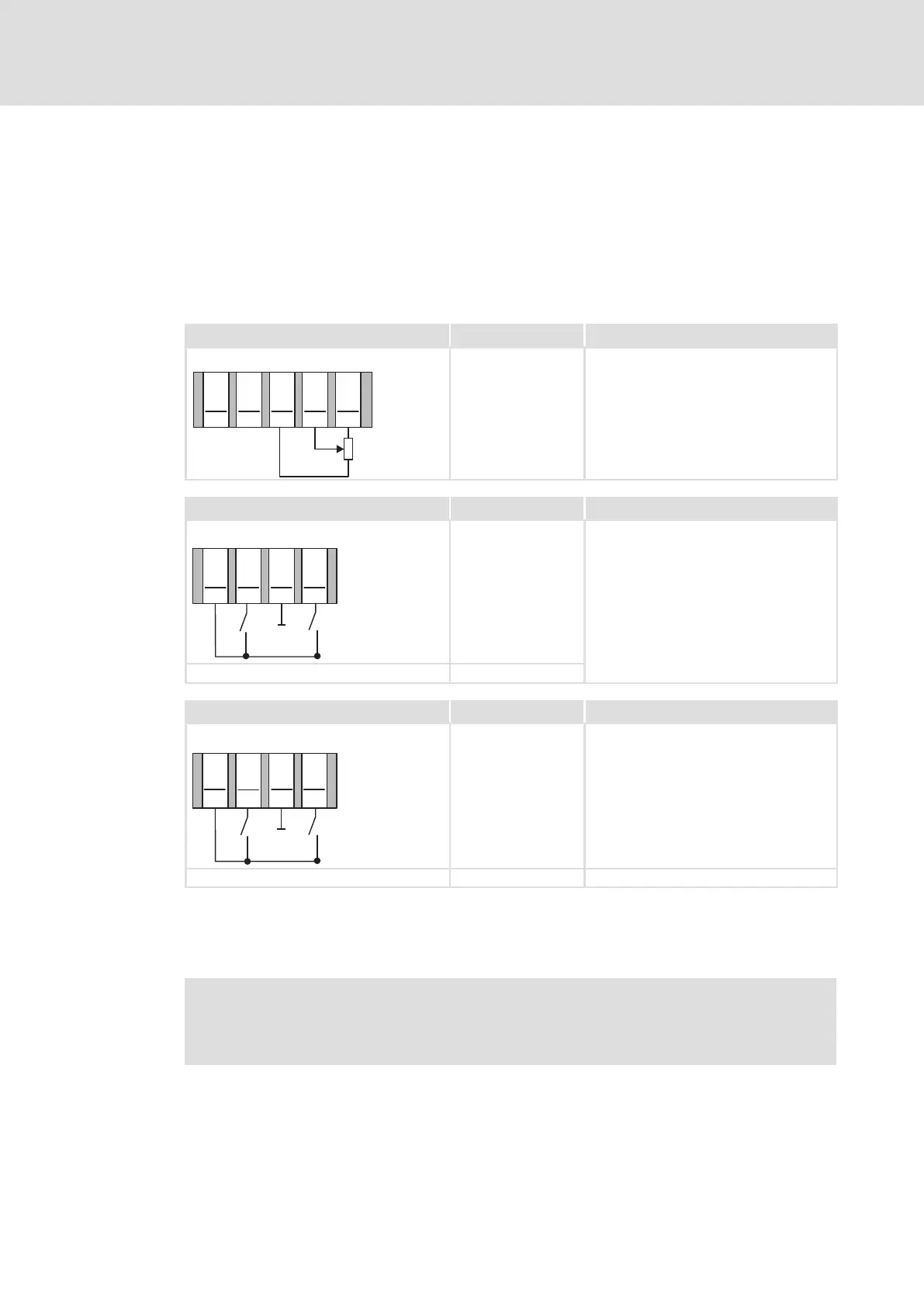
Analog inputs at X50 Assignment Terminal control
X50
24I
A1I
GA
A1U
AR
1
2
3
4
5
0...10V
1k
...
10k
Ω
Ω
A1U Setpoint selection
10 V (=100 %):
1500 min
−1
(with 4−pole motor)
Wiring of the digital outputs at X41 Assignment Terminal control
X41
24I
DI2
GIO
DI1
1
2
3
4
DI1
Fixed frequency 1 ... fixed frequency 3, see
table below
DI1 ... DI2: active = HIGH DI2
Wiring of the digital outputs at X42 Assignment Terminal control
X42
24I
GIO
DI3
1
2
3
4
DI4
DI3 DCB
DI3 ... DI4: active = HIGH DI4 Direction of rotation left/right (CCW/CW)
3. If you can be sure that the frequency inverter is in the default state (Lenze setting),
you can skip the following step. If not, establish the Lenze setting of the frequency
inverter. We recommend to use the keypad for this.
Note!
The application "actuating drive speed" is implemented with the Lenze
setting.