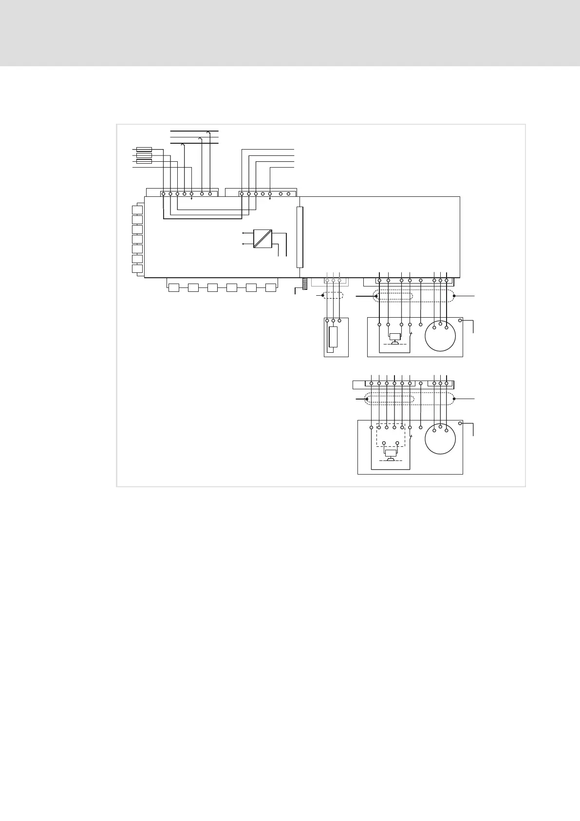
Electrical installation − EMS version
Devices in a power range of 0.75 ... 4 kW (3/PE AC 400 V)
Example circuits
7
119
EDS84DPS424 EN 5.0
Power wave / DECA bus
M
3~
U
V
W
+
+
BRK1
T1 T2
T
h
+
-
"
"
0
"
"
6
4
1
2
3
X21
+
c
1
2
3
a
5
M
3~
U
V
W
+
+
T1 T2
T
h
BRK1
+
-
~~
S1 S2
GL1
1
E84Dx...
5
8
4
6
1
7
3
X21
+
1 2
X20
+
X80
X43
X42X41
X32
X31
+
1
112
3
4
12
+
X10
1
11
2
3
4 12
+
X11
+
-
+24 V
GND
U24
=
X46
X47
X48
X45
X81
X82
X34
BRW1
12
+
"
E84D x.../
E84D x
P
D
3/PE AC
380 ... 500 V
L1
L2
L3
PE
L1
L2
L3
PE
Data+
SS1
Data-
E84DWSP060_B
E84DPx... / E84DDx... 8400 protec EMS controller, power wave / DECA bus
X10: L1, L2, L3, PE Mains voltage
X10: data±, SS1 EMS: Signalling bars, control bars
X11 Mains voltage loop−through technique (optional)
X31 ... X32 Fieldbus communication
X34 CANopen master PLC
X41 ... X43 DIO
X45 ... X48 EMS: Further DIO
X80 SSI
X81/X82 EMS: RS485/422
M Motor
Motor connection system: Plug type Q8/0
Motor connection system: Plug type Modular
T
h
PTC thermistor (PTC) or thermal contact (NC contact)
BRK1 Spring−applied brake
GL1 Spring−applied brake control
BRW1 External brake resistor at the optional terminal X20
U24 Supply voltage 24 V internal