Electrical installation − EMS version
Control terminals
Digital inputs and outputs
7
129
EDS84DPS424 EN 5.0
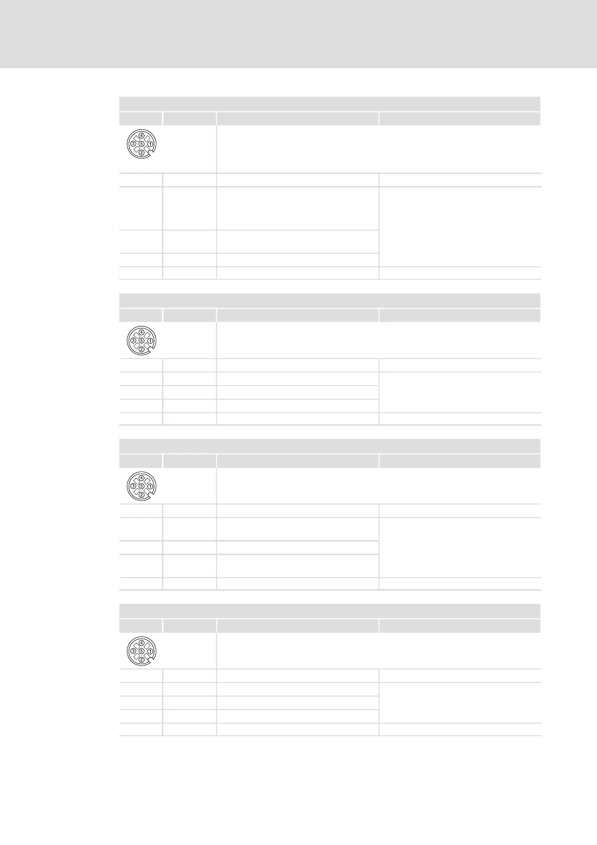
X43 − digital inputs DI5, DI6
Pin Signal Description Data
Type M12, 5−pole sockets
84DPSO05_5
1 24O 24 V supply of the external sensors
2 DI6 Digital input 6 According to IEC61131−2, type 1
or
Single−channel frequency input, 0 ... 10
kHz
3 GIO Reference potential HIGH
LOW
+15 .... +30 V DC
0 ... +5 V
4
DI5 Digital input 5 8 mA at 24 V DC
5 n. c. Not assigned
X45 − digital inputs DI7, DI8
Pin Signal Description Data
84DPSO05_5
Type M12, 5−pole sockets
1 24O 24 V supply of the external sensors
2 DI8 Digital input 8 HIGH +15 .... +30 V DC
3 GIO Reference potential LOW 0 ... +5 V
4
DI7 Digital input 7 8 mA at 24 V DC
5 n. c. Not assigned
X46 − digital inputs DI9, DI10
Pin Signal Description Data
84DPSO05_5
Type M12, 5−pole sockets
1 24O 24 V supply of the external sensors
2 DI10
(DO4)
Digital input 10
(also available as digital output)
HIGH +15 .... +30 V DC
3 GIO Reference potential LOW 0 ... +5 V
4 DI9
(DO3)
Digital input 9
(also available as digital output)
8 mA at 24 V DC
5 n. c. Not assigned
X47 − digital inputs DI11, DI12
Pin Signal Description Data
84DPSO05_5
Type M12, 5−pole sockets
1 24O 24 V supply of the external sensors
2 DI12 Digital input 12 HIGH +15 .... +30 V DC
3 GIO Reference potential LOW 0 ... +5 V
4 DI11 Digital input 11 8 mA at 24 V DC
5 n. c. Not assigned