Technical data
Terminal description
4
60
EDS84DPS424 EN 5.0
EMS version
E84DWGA015 a
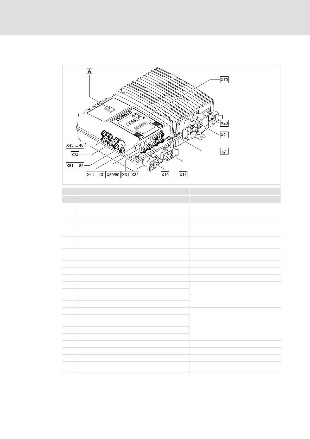
Operational controls and connections
Pos. Function Description
Control element Optional
PE connection for M6 ring cable lug
X10 Mains and 24−V buffer voltage DESINA Q4/2, pins
X11 Optional: Loop−through technique − mains and 24−V
buffer voltage
DESINA Q4/2, sockets (optional)
Optional: Molex
X20 Optional: For external brake resistor Q5/0, sockets (optional)
Optional: Molex
X21 Motor, temperature monitoring and motor holding
brake
Q8/0, Modular or 10E, sockets
X31 Fieldbus input M12, A−coded, pins
X32 Fieldbus output M12, A−coded, sockets
X34 CANopen master PLC M12, 5−pole, A−coded, sockets
X41 Digital inputs DI1 and DI2
M12, 5−pole sockets, A−coded
X42 Digital inputs DI3 and DI4, also configurable as digital
outputs DO1 and DO2
X43 Digital inputs DI5 and DI6
X45
Digital inputs DI7 and DI8
M12, 5−pole, A−coded, sockets
X46
Digital inputs DI9 and DI10, also configurable as digital
outputs DO3 and DO4
X47
Digital inputs DI11 and DI12
X48
Digital inputs DI13 and DI14
X50 Analog input AI, AU M12, 5−pole sockets, A−coded
X70 Diagnostics Socket RJ69
X80 Synchronous serial interface (SSI) M12, 8−pole sockets, A−coded
X81
X82
RS485/RS422 M12, 8−pole, A−coded, sockets