Electrical installation − HighLine/StateLine version
Control terminals
Digital inputs and outputs
6
96
EDS84DPS424 EN 5.0
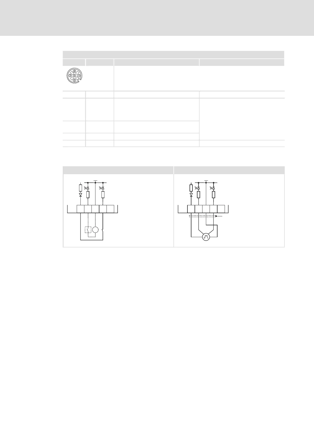
X43 − digital inputs DI5, DI6
Pin Signal Description Data
Type M12, 5−pole sockets
84DPSO05_5
1 24O 24 V supply of the external sensors
2 DI6 Digital input 6 According to IEC61131−2, type 1
or
Single−channel frequency input, 0 ... 10
kHz
3 GIO Reference potential HIGH
LOW
+15 .... +30 V DC
0 ... +5 V
4
DI5 Digital input 5 8 mA at 24 V DC
5 n. c. Not assigned
Example circuit
DI1
S1
X41
GND-IO
GIO
24O
3.3k
3.3k
DI2
S2
=
-
+
DI1
X41
GND-IO
GIO
24O
3.3k
3.3k
DI2
"
8400DIO045 8400DIO022
Fig. 6−6 Wiring examples of the digital inputs
Wiring of digital inputs, examples:
S1 Potential−free contact, at internal 24 V supply
S2 Signal source, e.g. PLC or with external 24 V supply
Connection of an HTL incremental encoder with a maximum input frequency of
100 kHz
DI1 track A
DI2 track B
X41 Plugs for digital inputs X41 ... X43
GIO Ground reference potential for the digital inputs and outputs (GND−IO)