4×analog input
5
The modular system
5.10
l
5.10-3
EDSPM-TXXX-3.0-04/2004
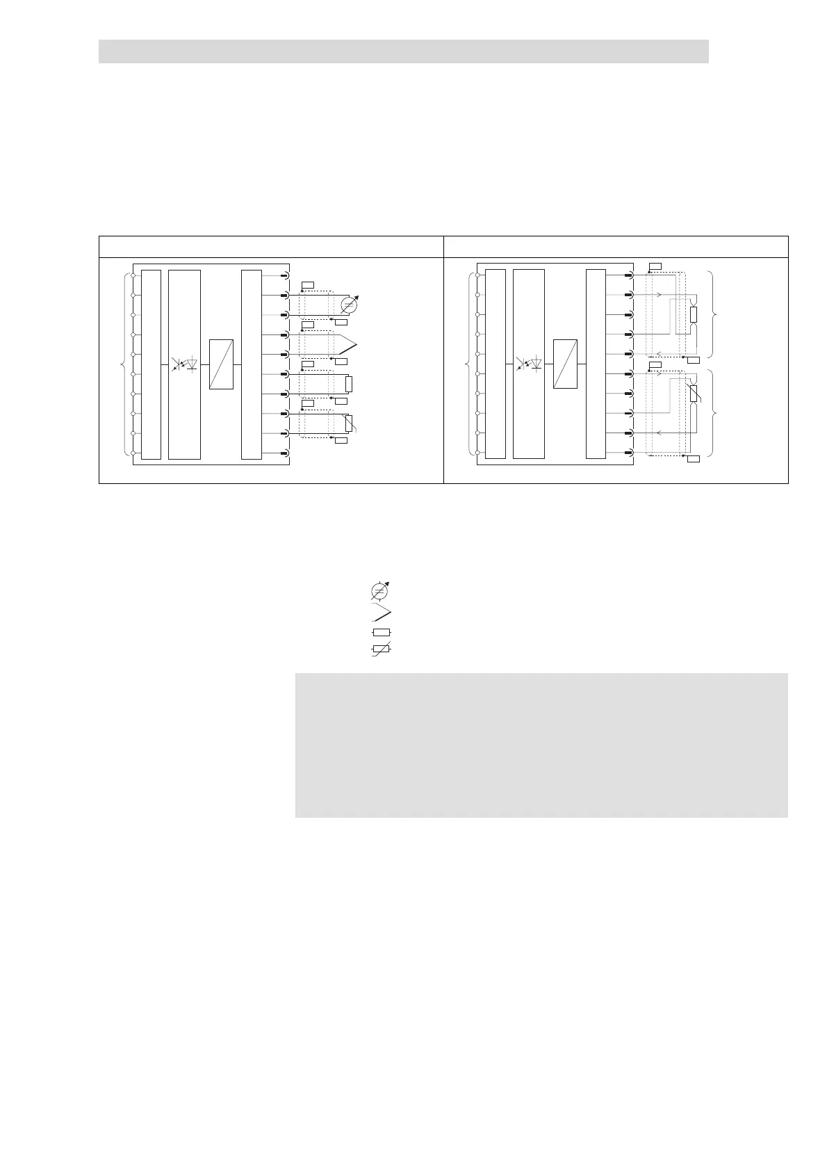
Connection
Two-wire connection
Four-wire connection
2
1
3
5
7
9
10
4
6
8
.
D
A
µP
MUX
PES
PES
PES
PES
PES
PES
PES
PES
D
A
µP
MUX
9
10
+U
+U
-U
-U
I
I
I
I
8
7
6
5
4
3
2
1
1
0
PES
PES
PES
PES
.
epm-t036 epm-t033
Fig. 5.10-3 Sensor connection
Analog input E.0
Analog input E.2
)
Connection to backplane bus
PES HF shield termination through large-surface connection to PE
Sensor:
Voltage or current source
Thermal element
Resistor
Resistor, temperature-dependent
Note!
z
Short-circuit unused inputs (connect positive and negative
terminals) or deactivate them by assigning the function number
FF
h
.
z
The 4×analog input module does not supply any auxiliary
voltage for sensors. For information on how to connect sensors,
please refer to the relevant sensor documentation.
 Loading...