4×analog output
5
The modular system
5.11
l
5.11-2
EDSPM-TXXX-3.0-04/2004
AO 4x12BIT
Q0
M0
Q1
M1
Q2
M2
Q3
M3
M
L+
1
2
3
4
5
6
7
8
9
L
10
EPM – T320 1A 10
1
2
0
2
1
3
5
7
9
10
4
6
8
.
D
A
D
A
D
A
D
A
µP
PES
PES
PES
PES
PES
PES
PES
PES
–
+
DC 24 V
(DC 19.2
… 28.8 V)
epm-t030 epm-t037
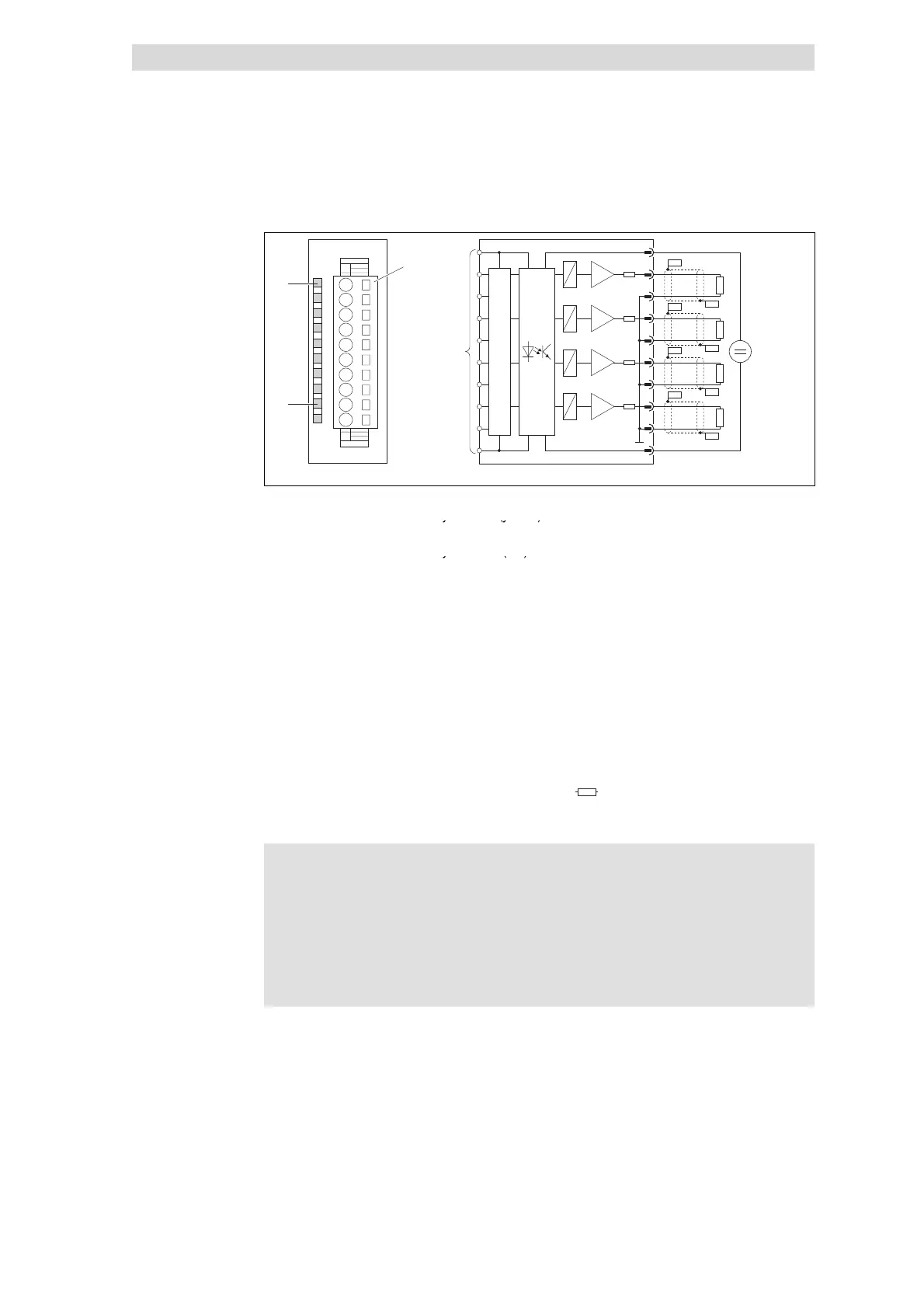
Fig. 5.11-2 Front view and connection of 4×analog output
Status display L+; LED (yellow) is lit
Terminal strip assignment details
when a supply voltage is applied
1 DC 24 V supply voltage
Status display M3; LED (red) is lit in
2 Analog output A.0
case of the following faults:
Short-circuit on voltage output
3 GND1 (reference potential for
analog signals)
Open circuit on current output
4 Analog output A.1
CAN gateway is not supplied with
volta
e
5 GND1 (reference potential for
analog signals)
6 Analog output A.2
7 GND1 (reference potential for
analog signals)
8 Analog output A.3
9 GND1 (reference potential for
analog signals)
10 GND (reference potential for
supply voltage)
)
Connection to backplane bus
Input resistor of actuator
PES HF shield termination through
large-surface connection to PE
Note!
z
Ensure correct polarity when connecting the actuators.
z
The 4×analog output module does not supply any auxiliary
voltage for actuators. For information on how to connect
actuators requiring auxiliary voltage, please refer to the relevant
actuator documentation.
z
Unused outputs remain unassigned.
Status display and terminal
assignment
 Loading...