5-4 Service Manual
7013-XXX
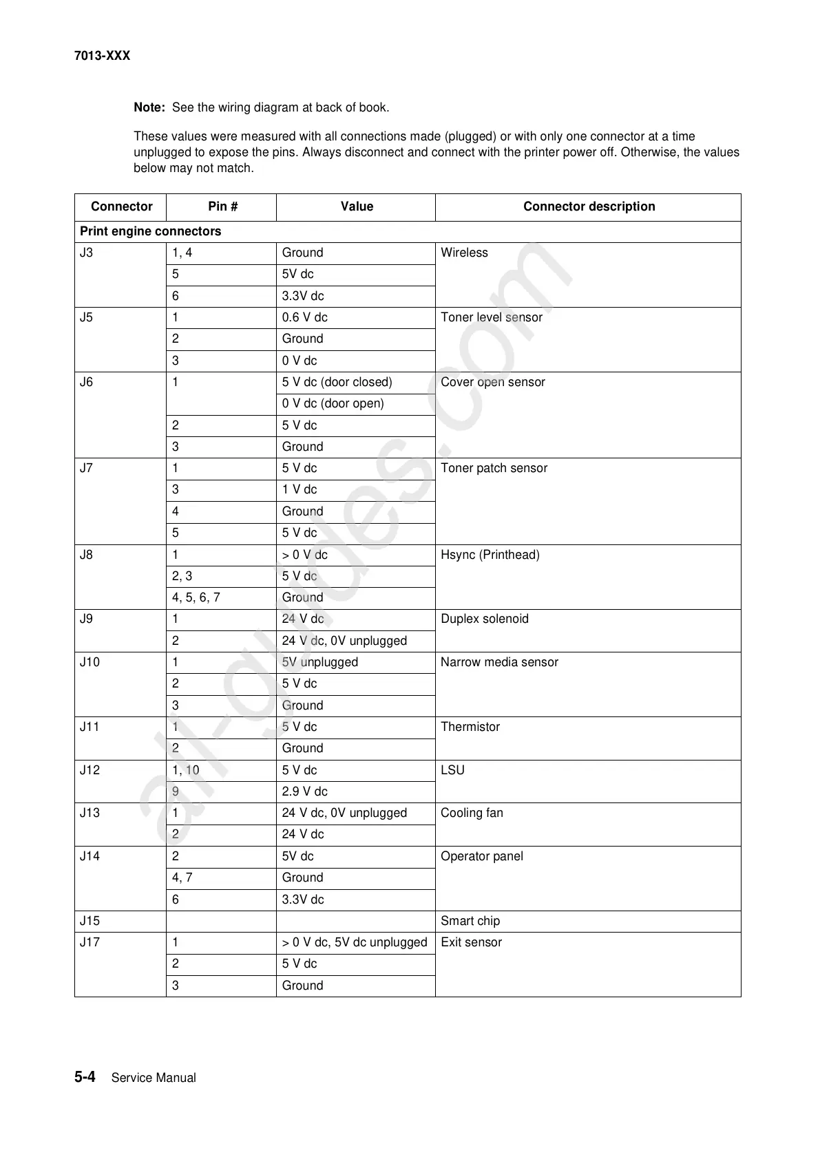
Note: See the wiring diagram at back of book.
These values were measured with all connections made (plugged) or with only one connector at a time
unplugged to expose the pins. Always disconnect and connect with the printer power off. Otherwise, the values
below may not match.
Connector Pin # Value Connector description
Print engine connectors
J3 1, 4 Ground Wireless
55V dc
63.3V dc
J5 1 0.6 V dc Toner level sensor
2 Ground
30 V dc
J6 1 5 V dc (door closed) Cover open sensor
0 V dc (door open)
25 V dc
3 Ground
J7 1 5 V dc Toner patch sensor
31 V dc
4 Ground
55 V dc
J8 1 > 0 V dc Hsync (Printhead)
2, 3 5 V dc
4, 5, 6, 7 Ground
J9 1 24 V dc Duplex solenoid
2 24 V dc, 0V unplugged
J10 1 5V unplugged Narrow media sensor
25 V dc
3 Ground
J11 1 5 V dc Thermistor
2 Ground
J12 1, 10 5 V dc LSU
92.9 V dc
J13 1 24 V dc, 0V unplugged Cooling fan
2 24 V dc
J14 2 5V dc Operator panel
4, 7 Ground
63.3V dc
J15 Smart chip
J17 1 > 0 V dc, 5V dc unplugged Exit sensor
25 V dc
3 Ground