4-20 Service Manual
5025-2xx, 4xx
Controller board removal
See Controller board—C544n, C544dn, C544dw, Controller board—C540n, C543dn, C540dw, or
“Controller board—C546dn only” on page 7-7 for the part number.
Warning: Observe all ESD precautions while handling electrostatic-discharge sensitive parts. See “Handling
ESD-sensitive parts” on page 4-1.
Warning: Replace one of the following components, and perform a POR before replacing a second
component. Never replace both of the components without performing a POR after installing each
one, or the printer may be rendered inoperable:
• Operator panel assembly
• Controller board
Warning: Never install and remove components listed above as a method of troubleshooting components.
Once one of these components has been installed in a printer, and the printer is powered
on, the component cannot be used in another printer. The component must be returned to
the manufacturer.
1. Remove the rear shield. See “Top cover assembly removal” on page 4-13.
2. Disconnect all the cables from the controller board.
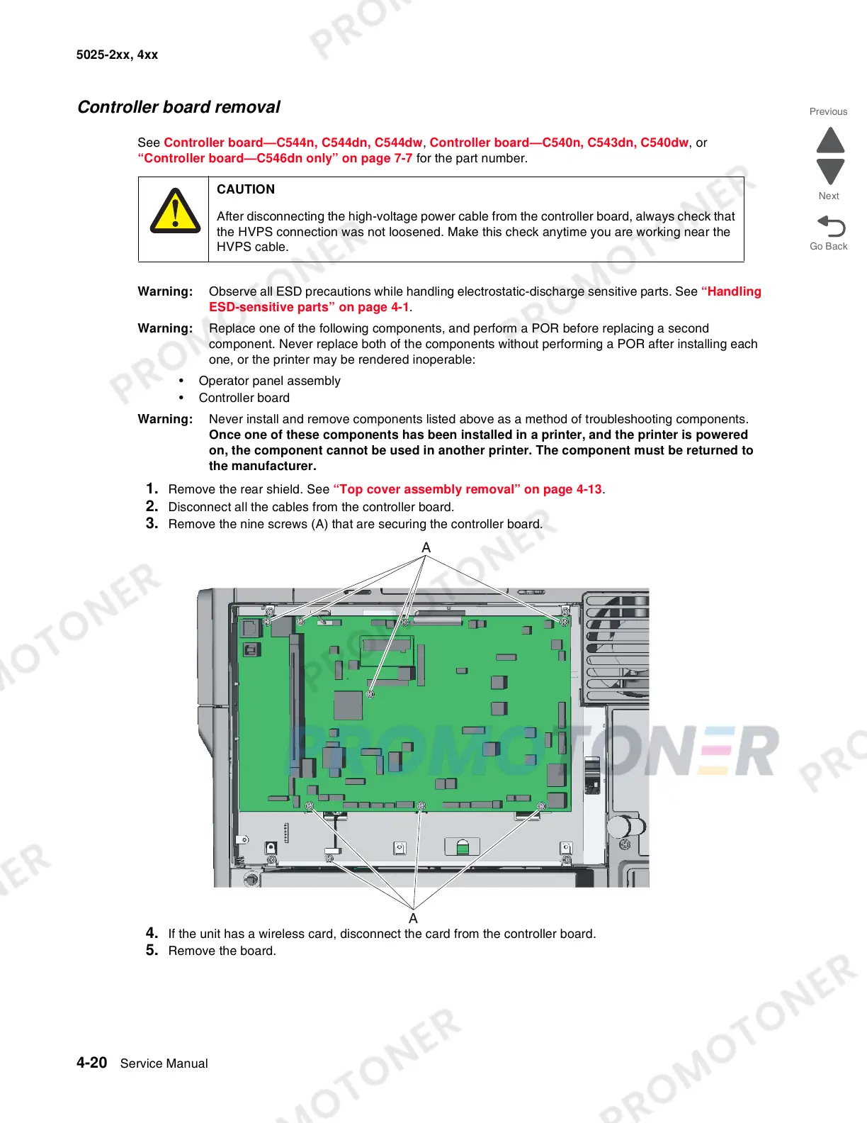
3. Remove the nine screws (A) that are securing the controller board.
4. If the unit has a wireless card, disconnect the card from the controller board.
5. Remove the board.
CAUTION
After disconnecting the high-voltage power cable from the controller board, always check that
the HVPS connection was not loosened. Make this check anytime you are working near the
HVPS cable.