Diagnostic information 2-41
5025-2xx, 4xx
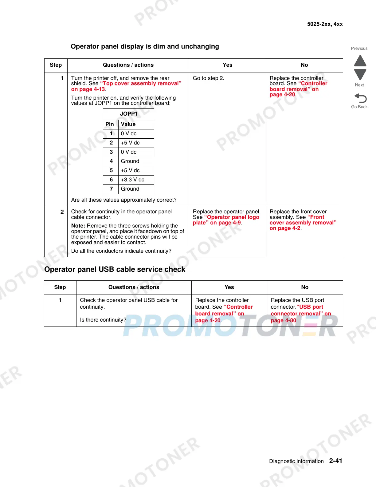
Operator panel display is dim and unchanging
Operator panel USB cable service check
Step Questions / actions Yes No
1 Turn the printer off, and remove the rear
shield. See “Top cover assembly removal”
on page 4-13.
Turn the printer on, and verify the following
values at JOPP1 on the controller board:
Are all these values approximately correct?
Go to step 2. Replace the controller
board. See “Controller
board removal” on
page 4-20.
2
Check for continuity in the operator panel
cable connector.
Note: Remove the three screws holding the
operator panel, and place it facedown on top of
the printer. The cable connector pins will be
exposed and easier to contact.
Do all the conductors indicate continuity?
Replace the operator panel.
See “Operator panel logo
plate” on page 4-9.
Replace the front cover
assembly. See “Front
cover assembly removal”
on page 4-2.
Step Questions / actions Yes No
1 Check the operator panel USB cable for
continuity.
Is there continuity?
Replace the controller
board. See “Controller
board removal” on
page 4-20.
Replace the USB port
connector.“USB port
connector removal” on
page 4-80
JOPP1
Pin Value
1 0 V dc
2 +5 V dc
3 0 V dc
4 Ground
5 +5 V dc
6 +3.3 V dc
7 Ground