Page 17 of 96
© 2020 LINAK A/S
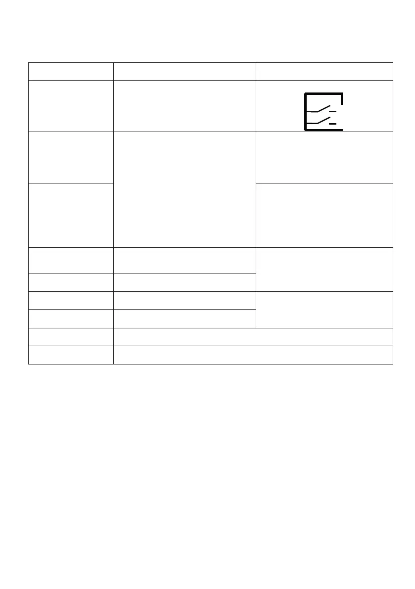
Actuator with endstop signal output
I/O specifications:
Input/Output Specification Comments
Description The actuator can be equipped with elec-
tronically controlled endstop signals out.
See connection diagram,
fig. 2 on page 17
Brown 12, 24, 36 or 48 VDC (+/-)
12 V ± 20%
24 V ± 10%
36 V ± 10%
48 V ± 10%
Under normal conditions:
12 V, max. 26 A depending on load
24 V, max. 13 A depending on load
36 V, max. 10 A depending on load
48 V, max. 6.5 A depending on load
To extend actuator:
Connect Brown to positive
To retract actuator:
Connect Brown to negative
Blue To extend actuator:
Connect Blue to negative
To retract actuator:
Connect Blue to positive
Red Signal power supply (+)
12-24VDC
Current consumption:
Max. 40mA, also when the actuator is
not running
Black Signal power supply GND (-)
Green Endstop signal out Output voltage min. V
IN
- 2V
Source current max. 100mA
NOT potential free
Yellow Endstop signal in
Violet Not to be connected
White Not to be connected
IN
OUT